54
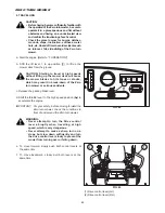
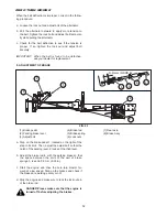
12. ADJUSTMENT PHASE OF DRIVE CONTROL
LEVER
After adjusting the straight drive operation of the mower,
perform the following steps when the amount of depres-
sion of the left and right control levers are not the same.
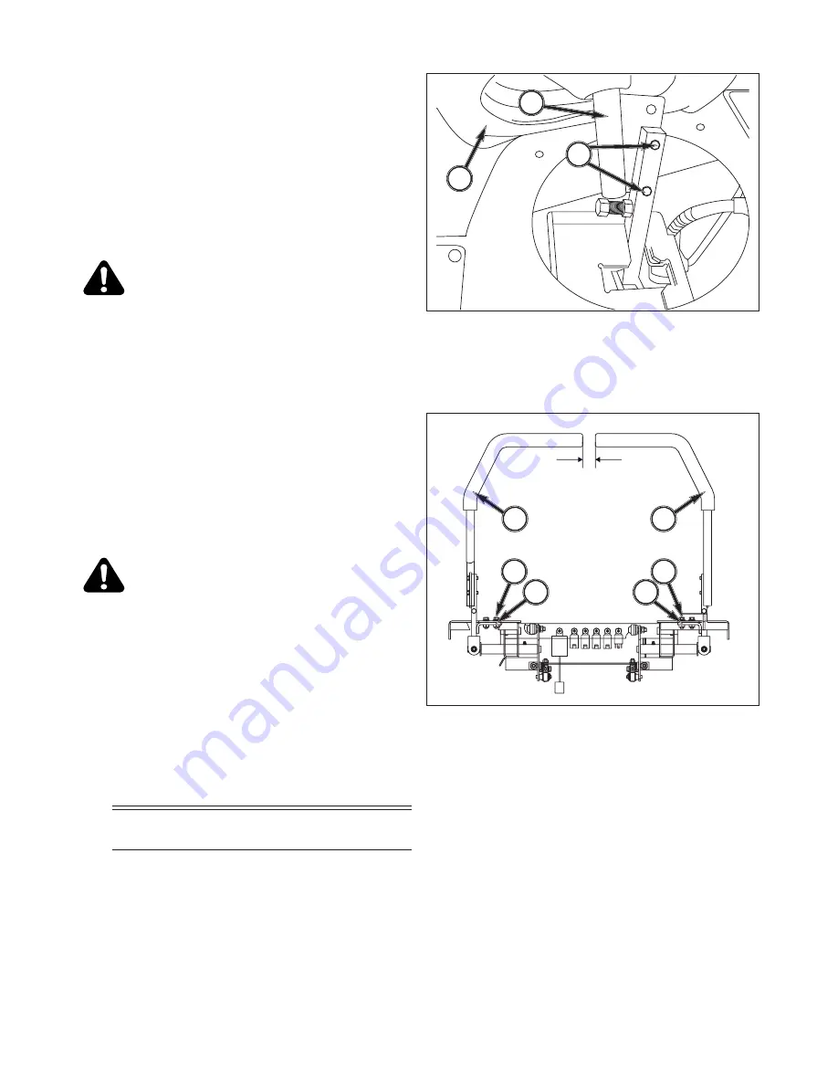
a. Remove the boots,3, of both drive control levers,1.
b. Loosen the adjust bolts,2, and adjust the depression
of both drive control levers.
c. Re-install the boots to their original position.
DANGER:Please make sure that the engine is
turned off before adjusting the depression of
the control levers using the adjust bolt.
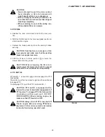
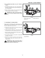
13. ADJUSTMENT CLEARANCE OF DRIVE CONTROL
LEVER
a. Remove the boots of both drive control levers.
b. Loosen the adjust bolts,3, to adjust the adjust plate.
c. Adjust the control levers so that their clearance is
about 35 mm (1.38 in). Tighten the adjust bolts.
d. Re-install the boots to their original position.
DANGER:Please make sure that the engine is
turned off before adjusting the adjust bolts.
Insufficient clearance in both left and right
control levers can lead to abnormal operation
of the zero-turn mower. Therefore, the clear-
ance limit prescribed above should be main-
tained.
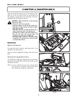
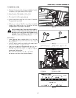
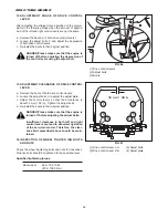
14. INSPECTION OF WHEEL TIGHTEN ING BOLTS
AND NUTS
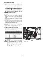
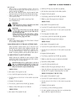
Check the wheel tightening bolts and nuts for looseness.
All loose bolts should be tightened to the specified level.
Specified tightening torque:
Rear wheel:
64.3~75.9 ft-lbs
(87.2~102.9 N.m)
(1) Drive control levers
(2) Adjust bolts
(3) Boots
(1) Drive control lever L.H.
(3) Adjust bolts
(2) Drive control lever R.H.
(4) Adjust plate
ZERO TURN MOWER
1
3
2
1
3
4
2
35 mm (1.38 in)
3
4
FIG. 66
FIG. 67
Содержание SZ330
Страница 1: ...I S E K I Z E R O T U R N M O W E R ZERO TURN MOWER MOWER DECKS SZ330 SSM60 SSM72 ...
Страница 21: ...20 9 29 Check that all safety devices are in place and oper ating properly ZERO TURN MOWER ...
Страница 71: ...ZERO TURN MOWER 70 ...
Страница 94: ...95 CHAPTER 7 TROUBLESHOOTING ...
Страница 95: ...96 ZERO TURN MOWER ...

