4
Maintenance and adjustment
78
Procedure
1. Insert a tommy bar in the hole at the
end of the clutch operating shaft (1)
and rotate it clockwise until resistance
is felt.
2. Slacken the clamp bolt (2) securing
the arm to the shaft and set pedal free
travel that will give a free pedal move-
ment of about 16 mm (0.6 in) at the
pad.
3. Retighten the clamp bolt (2). Press the
clutch pedal down through its full trav-
el five times, recheck the free travel
and readjust if necessary.
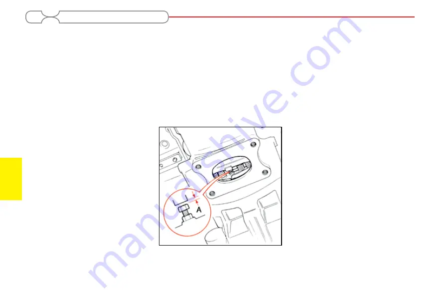
Live PTO clutch (Fig. 31)
Check the clutch setting every 1000
hours.
Check the clutch adjustment more fre-
quently if heavy PTO work has been in-
volved.
1. Remove the four bolts and the inspec-
tion cover from the underside of the
clutch housing.
2. With the stop control out, rotate the
engine until one of the three adjusters
is visible in the inspection aperture.
3. With the aid of a feeler gauge, check
the clearance ‘A’ between the bolt head
and the clutch plate. It should be 1,8
mm (0.070 in).
4. If adjustment is required, slacken the
nut and adjust the bolt to the correct
clearance and retighten the nut.
5. Carry out the same procedure for the
other two adjusters and replace the in-
spection cover.
Fig. 31:
BRAKES
Check the brakes every 250 hours,
or more frequently if heavy work is in-
volved.
Procedure to adjust the brakes:
1. Jack up the tractor until both rear
wheels are clear of the ground.
2. Disengage the brake return springs and
release the parking brake.
3. Unlatch the brake pedals.
4. Measure the height of the right-hand
pedal from the footstep, when fully up.
5. Apply a light load to the brake pedal and
remeasure the pedal height. The pedal
free travel should be 25 mm (1 in)
6. If adjustment is necessary, turn the
19 mm across flats adjuster nut (Fig.
32) on the right-hand rear axle brake
actuating lever clockwise to reduce
free travel and counter clockwise to
increase free travel.
7. Having adjusted the right-hand pedal,
adjust the left-hand pedal to match for
height so that the latch freely engages.
8. Reconnect the brake return springs.
9. Road test the tractor, and check the
brakes for binding or pulling to one
Содержание ITM 470
Страница 1: ...Iran Tractor Industrial Group OPERATOR INSTRUCTION BOOK Tractor Model ITM 470 2WD 4WD...
Страница 3: ......
Страница 5: ......
Страница 23: ...General information 1 16 The location of safety decals...
Страница 24: ...1 General information 17 The location of general decals...
Страница 25: ......
Страница 39: ......
Страница 65: ......
Страница 108: ...4 Maintenance and adjustment 101 WIRING DIAGRAM Fig 73 Complete circuitry of tractor...
Страница 113: ......


