background image

Sabre 1555 RFID and Bar Code Reader Service Manual 

2-32 

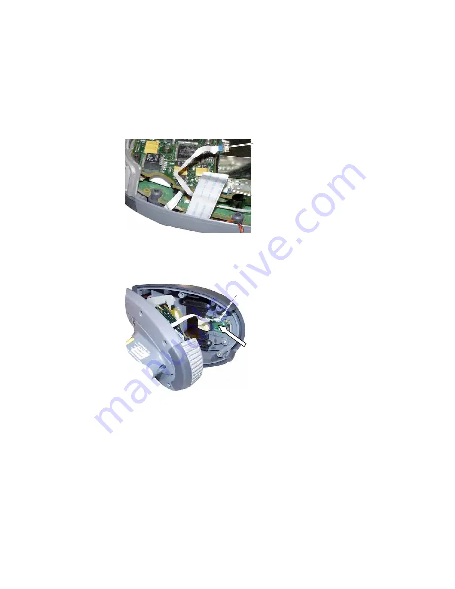
7. Place a small piece of Kapton tape over the 8-pin connector and flex cable to secure

them.

8. Slide the excess 8-pin flex cable into the gap between the RF board and the digital

board. Fold the excess 12-pin flex cable over the top of the digital board.

12-pin flex cable
installed and
folded over

8-pin flex cable
installed on back
of scan engine

9. Insert the 10-pin flex cable into the connector on the keyboard PCB. The flex cable

contacts should face the center of the 1555.

10-pin flex cable

Contacts to this
side of connector

Содержание Sabre 1555 RFID

Страница 1: ...Sabre 1555 RFID and Bar Code Reader Service Manual...

Страница 2: ...itten permission of Intermec Information and specifications in this manual are subject to change without notice 2002 by Intermec Technologies Corporation All Rights Reserved The word Intermec the Inte...

Страница 3: ...xit Window 2 10 Opening the 1555 2 12 Replacing the Piezo Assembly 2 14 Removing and Replacing the Digital Board 2 15 Replacing the RF Board Assembly 2 18 Removing and Replacing the Scan Engine 2 20 R...

Страница 4: ...de Depth of Field Test 3 5 Setting Up for the Test 3 5 RFID Functional Test 3 7 Radiated Tag Read Test 3 7 Open Air Tag Read Test 3 9 Exploded View and Spare Parts List Exploded View 4 3 Spare Parts L...

Страница 5: ...g Intermec equipment You can be seriously injured and equipment and data can be damaged if you do not follow the safety warnings and cautions Do not repair or adjust alone Do not repair or adjust ener...

Страница 6: ...destruction or corruption or loss of data Optics Always wear finger cots or non powdered latex gloves when handling optical parts such as the exit window Follow ESD Procedures Follow ESD Procedures T...

Страница 7: ...spare parts list This manual is written for service technicians who will troubleshoot and repair the 1555 For information on operating the Sabre 1555 see the Sabre 1555 RFID Bar Code Reader Getting St...

Страница 8: ...alexdaddy...

Страница 9: ...Troubleshooting the 1555 1...

Страница 10: ...alexdaddy...

Страница 11: ...d and program radio frequency identification RFID tags There are two models of the 1555 The standard model is powered by an external AC power supply P N 070826 and is connected to a host PC via a stat...

Страница 12: ...make sure that the body and shield of the scan engine are not grounded to the RF board 3 Replace the handle PCB as described on page 2 5 Aiming beam does not appear during Scanning and LED Operation...

Страница 13: ...reads inconsistently 1555 fails RFID Functional Test 1 Open the case as described on page 2 12 For 915 MHz versions manufactured before December 2001 make sure the 1555 has the correct revision of the...

Страница 14: ...gital board for the correct revision Rev C printed on board OR large inductor mounted on board surface during rework Large inductor For 2 4 GHz versions manufactured in or after September 2001 and for...

Страница 15: ...Replacing Parts in the 1555 2...

Страница 16: ...alexdaddy...

Страница 17: ...this chapter to disassemble and replace parts in the 1555 Removing and Replacing the Extender Wedge PDT 1555 only To replace the extender wedge you need Wedge assembly P N 070326 001 You need these to...

Страница 18: ...xtender wedge 1 Use tweezers to install the new wedge flex cable in the connector on the handle PCB The flex cable contacts must face the PCB 2 Press the extender wedge into the bottom of the handle M...

Страница 19: ...from the 1555 To remove the handle you need the following tools Torque driver with a 10 Torx bit To remove the handle or handle PCB 1 For a PDT 1555 remove the battery pack and then remove the extend...

Страница 20: ...flex cables from the handle PCB and remove the PCB You are now ready to replace the handle PCB For help continue with the next procedure To replace the handle PCB or handle assembly 1 Remove the hand...

Страница 21: ...ctor 4 Install the 12 pin flex cable in its connector The contacts must face away from the PCB Be sure the flex cable is seated correctly 5 Install the 10 pin flex cable in its connector The contacts...

Страница 22: ...7 Install the piezo connector in the jack on the end of the handle PCB Piezo jack 8 Dress the three flex cables as shown in the next illustration and wrap a 5 cm 2 in piece of Kapton tape over the fl...

Страница 23: ...dle PCB into these alignment grooves 10 Install the handle assembly on the lower case using three 4 40 x 0 25 Torx screws Torque the screws to 0 791 Nm 7 0 lb in 11 For a standard 1555 reinstall the c...

Страница 24: ...rque driver with a Torx bit To replace the exit window 1 Remove the FCC label from the bottom of the case 2 Remove the six Torx screws from the bottom of the case 3 Carefully pull the front end of the...

Страница 25: ...cutout areas on the sides of the digital board and push the upper and lower shells together Note Be sure the flex cables are not pinched between the shells 7 Install six 4 40 x 0 75 Torx screws in the...

Страница 26: ...the case 2 Remove the six Torx screws from the bottom of the case 3 Hold the 1555 with one thumb on the heatsink and carefully pull the upper case assembly from the lower case Because the RF board ant...

Страница 27: ...tor on the handle PCB The upper case assembly is now disconnected from the 1555 7 Place the RF board assembly in the lower shell You are now ready to replace other parts as listed in the next table To...

Страница 28: ...he piezo assembly 1 Open the 1555 and disconnect the upper case assembly as described on page 2 12 2 Use a small slotted screwdriver to pry the piezo assembly out of the upper case 3 Peel the backing...

Страница 29: ...a 10 Torx bit To remove the digital board 1 Open the 1555 and disconnect the upper case assembly as described on page 2 12 2 Disconnect the 8 pin flex cable from its connector on the rear of the scan...

Страница 30: ...the digital board up until it clears the heatsink Heatsink 6 Slide the digital board out of its holders on the RF board assembly and tilt it up on its side edge 7 Unlatch the 25 pin connector on the u...

Страница 31: ...contacts must face away from the digital board Be sure the flex cable is seated correctly and latch the connector 2 Tilt the digital board down into position over the RF board assembly and slide the e...

Страница 32: ...page 2 30 Replacing the RF Board Assembly To replace the RF board assembly you need the following parts RF board assembly shielded 2 4 GHz P N A050017 01 or A050017E 01 exchange part or RF board asse...

Страница 33: ...l board assembly from the RF board The digital board is still connected to the RF board by a 25 pin flex cable 2 4 GHz version 6 On the RF board unlatch the 25 pin connector and disconnect the flex ca...

Страница 34: ...into the RF board The RF board assembly is ready to be installed in the lower shell For help see Reassembling the 1555 on page 2 30 Removing and Replacing the Scan Engine The scan engine is installed...

Страница 35: ...ly as described on page 2 12 2 Disconnect the 8 pin flex cable from the connector on the rear of the scan engine 8 pin connector 3 Tilt the RF board assembly up and remove the two Torx screws on the u...

Страница 36: ...y Make sure the scan engine connector faces away from the shield or antenna Scan engine connector 2 4 GHz version 915 MHz version 6 Install the two Phillips screws to hold the scan engine in place Tor...

Страница 37: ...sis assembly 915 MHz 1555 you need Shield and chassis assembly P N 072376S 001 To replace the antenna assembly 2 4 GHz 1555 you need Antenna assembly P N A050014 01 You need these tools Torque driver...

Страница 38: ...a 2 4 GHz 1555 unplug the antenna cable from its connector on the RF board For a 915 MHz 1555 continue with the next step Antenna cable connector Digital board not shown for clarity 4 Remove the Torx...

Страница 39: ...GHz 1555 6 Remove the two Phillips screws on the underside of the assembly and remove the scan engine Shield and chassis assembly 915 MHz Antenna assembly 2 4 GHz 7 Do one of the following To replace...

Страница 40: ...ews to hold the assembly onto the RF board Torque to 0 339 Nm 3 0 lb in 10 Install the Torx screw on top to hold the digital board in place on the RF board assembly Torque to 0 339 Nm 3 0 lb in 11 For...

Страница 41: ...ve the handle as described on page 2 5 2 Disconnect the piezo connector from the handle PCB Piezo jack 3 Disconnect the flex cables from the handle PCB and remove the PCB 4 Remove the FCC label from t...

Страница 42: ...case assembly and the RF board assembly keeping the RF board positioned in the upper case 7 Thread the flex cables through the opening in the new lower shell and place the handle in position on the s...

Страница 43: ...9 Nm 3 0 lb in 9 Install the handle PCB and handle assembly as described on page 2 6 The 1555 is ready for testing For help see the next chapter Replacing the Upper Case Assembly To replace the upper...

Страница 44: ...low these procedures to reassemble the 1555 and close the case You need this tool Torque driver with a Torx bit To reassemble the 1555 1 Route the flex cables as shown in the next illustration 2 4 GHz...

Страница 45: ...y strain on the piezo wiring 2 4 GHz 10 pin flex cable to this side 915 MHz All flex cables to this side 5 Insert the 12 pin flex cable into the connector on the digital board The contacts must face a...

Страница 46: ...gap between the RF board and the digital board Fold the excess 12 pin flex cable over the top of the digital board 12 pin flex cable installed and folded over 8 pin flex cable installed on back of sc...

Страница 47: ...ce a 2 5 mm 1 in piece of Kapton tape over the piezo wiring to secure it to the back of the LCD holder 11 Make sure the flex cables are clear of the cutout areas on the sides of the digital board Keep...

Страница 48: ...in the grooves on the front of the upper case assembly 13 Install six 4 40 x 0 75 Torx screws in the lower case to secure the shells together Torque the two screws closest to the scan window to 0 226...

Страница 49: ...Testing the 1555 3...

Страница 50: ...alexdaddy...

Страница 51: ...and 2 4 GHz PDT reader cable P N 3 634032 11 Charged battery P N 070067 Equipment Needed for Testing You need the following equipment to test the 1555 PC with Windows 95 or later High Performance Sca...

Страница 52: ...the 1555 until Tag Identify appears in the LCD The 1555 is now in RFID mode 6 Pull the trigger and verify that you can see the aiming beam on the blank surface Note The aiming beam appears as a point...

Страница 53: ...sults Use measuring aids to maintain the accuracy of the test The distances required for the test are as follows 197 0 cm 2 0 cm 77 75 in 0 75 in 86 0 cm 2 0 cm 33 75 in 0 75 in 45 0 cm 2 0 cm 17 75 i...

Страница 54: ...ation 1555EXX02XX02XX position the scanner window 197 0 cm 2 0 cm 77 75 in 0 75 in from the Scanner Test Card Scanner Position for Depth of Field Test A A Test distance 5 Be sure the 1555 is positione...

Страница 55: ...eads the code only once or not at all in 4 tries If the 1555 passes the test disconnect the power and continue with the RFID Functional Test If the 1555 fails the test there is a problem with reading...

Страница 56: ...to the 1555 4 On the desktop PC start the RFID Host Application P N A110006 The main screen appears 5 Set parameters in the RFID Host Application as follows Reader Module Selection Sabre 1555 Passthro...

Страница 57: ...g the 1555 11 Click PRC to reset the 1555 and end the Radiated Tag Read Test Open Air Tag Read Test If the Shielded Test Chamber is not available perform this test to confirm the 1555 s ability to rea...

Страница 58: ...dule Selection Sabre 1555 Passthrough Mode Command PMC Freq 2450 MHz or 915 MHz as appropriate Receive Timeout 2000 mS Retries 0 Counted 100 Loops Loop Dly 0 Number of Tags Expected 1 6 Click COMM Set...

Страница 59: ...nd the target 11 Point the 1555 at the target and click RF Identify The 1555 will try to read the test tag 100 times and the RFID Host Application will keep track of how often the 1555 is able to read...

Страница 60: ...alexdaddy...

Страница 61: ...Exploded View and Spare Parts List 4...

Страница 62: ...alexdaddy...

Страница 63: ...e part in the exploded view and locate its callout number in the spare parts list 1 2 3 4 5 6 8 9 10 10 11 18 12 7 13 14 15 16 17 Screw 3 places Screw 6 places Screw 6 places Screw 2 places Screw 2 pl...

Страница 64: ...072376S 001 X X Exit window 7 S620 OPT 001 X X X X X RF board assembly 2 4 GHz 8 A050017 01 or A050017E 01 X X X RF board assembly 915 MHz 9 A050016 01 or A050016E 01 X X Lower shell 10 S620 CAS 002 E...

Страница 65: ...Corporate Headquarters 6001 36th Avenue West Everett Washington 98203 U S A tel 425 348 2600 fax 425 355 9551 www intermec com Sabre 1555 RFID and Bar Code Reader Service Manual 072529 001 072529 001...

Отзывы: