134
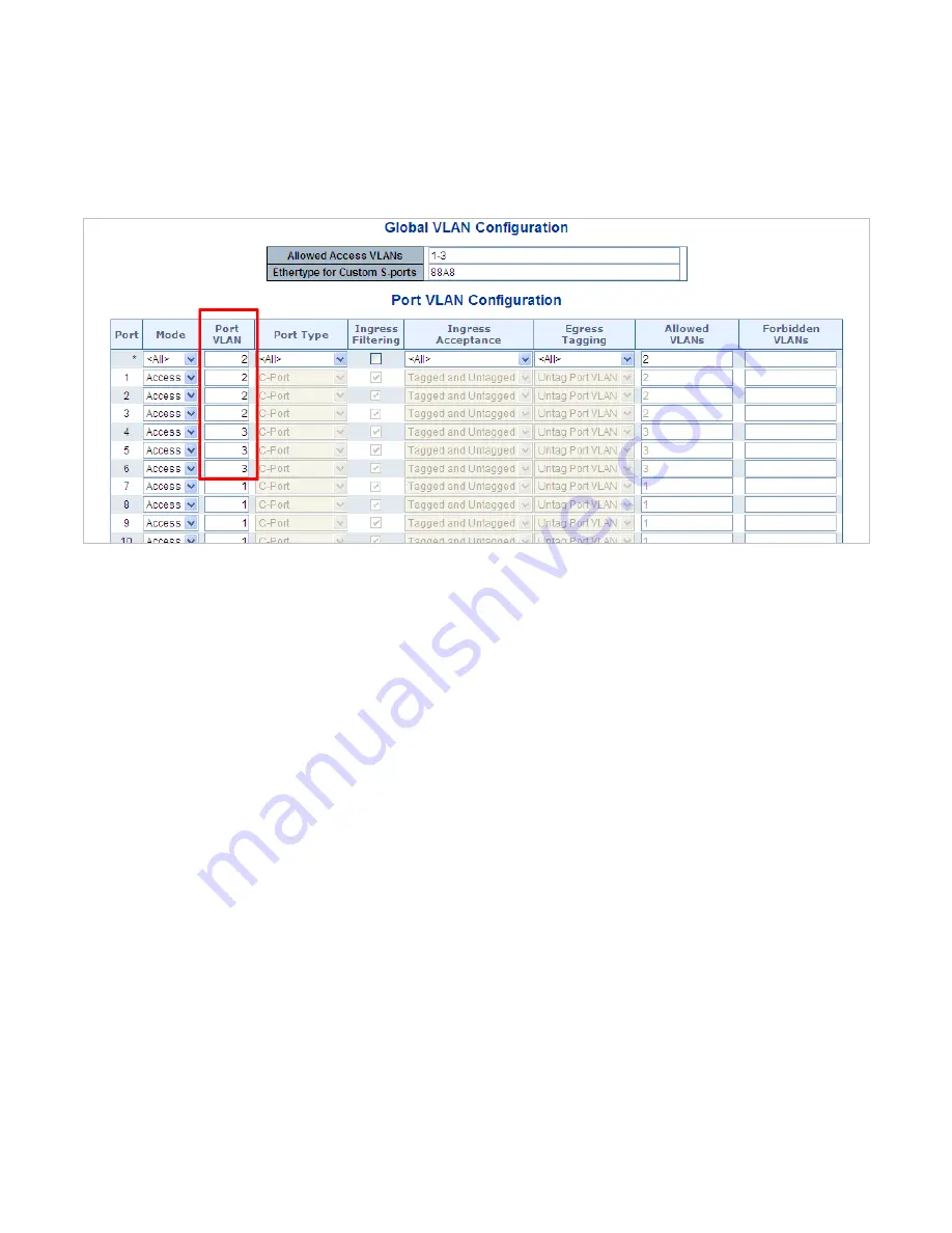
2. Assign VLAN Member and PVID for each port :
VLAN 2 : Port-1,Port-2 and Port-3
VLAN 3 : Port-4, Port-5 and Port-6
VLAN 1 : All other ports – Port-7~Port-48
Figure 4-6-13:
Changes Port VLAN of Port 1~3 to be VLAN2 and Port VLAN of Port 4~6 to be VLAN3
For the VLAN ports connecting to the hosts, please refer to 4.6.10.1 examples. The following steps will focus on the VLAN
Trunk
port
configuration.
1. Specify
Port-7
to be the 802.1Q VLAN
Trunk port
.
2. Assign
Port-7
to both
VLAN 2
and
VLAN 3
at the VLAN Member configuration Page.
3. Define
a
VLAN 1
as a
“Public Area”
that overlapping with both
VLAN 2 members
and
VLAN 3 members
.
4. Assign the VLAN Trunk Port to be the member of each VLAN – which wants to be aggregated. For this example, add
Port-7
to
be
VLAN 2
and
VLAN 3
member port.
5. Specify
Port-7
to be the 802.1Q VLAN
Trunk port
, and the Trunking port must be a
Tagged
port while egress. The Port-7
configuration is shown in
Figure 4-6-1
4
.
Содержание NS4702-24P-4S-4X
Страница 1: ...NS4702 24P 4S 4X User Manual P N 1072829 REV 00 01 ISS 14JUL14 ...
Страница 23: ...23 Storage Temperature 10 70 degrees C Relative Humidity 5 95 non condensing ...
Страница 164: ...164 Figure 4 8 2 Multicast Flooding ...
Страница 183: ...183 Figure 4 8 14 IGMP Snooping VLAN Configuration Page Screenshot ...
Страница 189: ...189 Figure 4 8 17 MLD Snooping Groups Information Page Screenshot ...
Страница 203: ...203 Buttons Click to apply changes Click to undo any changes made locally and revert to previously saved values ...
Страница 208: ...208 Figure 4 9 6 QoS Egress Port Tag Remarking Page Screenshot ...
Страница 218: ...218 Deletes the QCE The lowest plus sign adds a new entry at the bottom of the list of QCL ...
Страница 229: ...229 Figure 4 9 18 Voice VLAN Configuration Page Screenshot ...
Страница 252: ...252 Buttons Click to apply changes Click to undo any changes made locally and revert to previously saved values ...
Страница 291: ...291 measurement is 100 ms A value of 0 ms indicates that there hasn t been round trip communication with the server yet ...
Страница 299: ...299 Figure 4 11 17 Add User Properties Screen Figure 4 11 18 Add User Properties Screen ...
Страница 336: ...336 Figure 4 14 2 LLDPMED Configuration Page Screenshot ...
Страница 357: ...357 Figure 4 15 4 VeriPHY Cable Diagnostics Page Screenshot ...
Страница 367: ...367 ...
Страница 375: ...375 Figure 4 16 10 Port Power Consumption Screenshot Buttons Click to refresh the page immediately ...
Страница 391: ...391 ...


