


49
Enter System
Change PW
Help
Under standby mode, press [F1], enter function main menu
,
shows as P1.
System Password
:
_ _ _ _
In P1, choose “Enter System”, press[#] to confirm, LCD shows P2,
enter system password 2-0-0-3.
[Note] This password is system initial code
,
user can according to
their needs. Please refer to P42 for details.
System setting
If password is correct, it will enter P3, set system accordingly.
[Note] Use direction key [F1] or [F2] to choose or flip, or press [*] to
back to P1.
Perimeter Gate
Alarm Setting
Card
Time & Date
(1)
(2)
(3)
■
Perimeter gate station No. setting
In P3, choose “Perimeter Gate”, press [#] to confirm, LCD shows
P4, enter perimeter gate station No. and switch port No.
[Note] Valid scope for perimeter gate station No. is from 01
~
09
;
Switch port No. is the port No. which perimeter gate station
connects with switch.
Perimeter Gate:
01
Switch Port:
1
(4)
For example: Enter data according to hint, press [#] to confirm,
after successful registration, shows P5.
When finish setting, press [*] button to return to P3.
Perimeter Gate:
01
Switch Port:
3
(5)
In P7, choose “Register Single”, LCD shows P8, enter card No.
according to hint, press [#] to confirm, or put card on sensor of
perimeter gate station to finish single card registration.
After successful registration, P9 shows, enter next card’s No. or
put next card on sensor to begin new registration, or press [*] to
back to P7.
[Note] The ID card data is 10 digits ID card. When the ID card
number do not reach 10, then please add “0”at front.
Register Single
No. :0007234177
Successful.
(9)
1.Register single card
In P3, choose “Card”, LCD shows P7, proceed settings for IC/ID
card here.
[Note] Use direction key [F1] or [F2] to choose function or flip, or
press [*] to back to P3.
RegisterSingle
Register Multi
RegisterPatrol
Delete Single
(7)
Register Single
No.:
Press # confirm
(8)
■
Card setting
Alarm Setting
1+# Choose ON
0+# Choose OFF
Current OFF
(6)
■
Alarm setting
In P3 select “Alarm Setting”, press[#]to confirm, enter P6,
according the prompt to set the alarm ON/OFF.
[Note] Use direction key [F1]or[F2] to choose function, press[*]to
back to P3.
In P7, choose “Register Patrol”, press [#], LCD shows P10, enter
card No. according to hint, press [#] to confirm, after successful
registration, press[*] to back to P7.
Register Patrol
No.:
Press # confirm
(10)
2.Register patrol card
6
3. Product wiring diagram
This section will introduce wiring diagram for every parts’ port in detail.
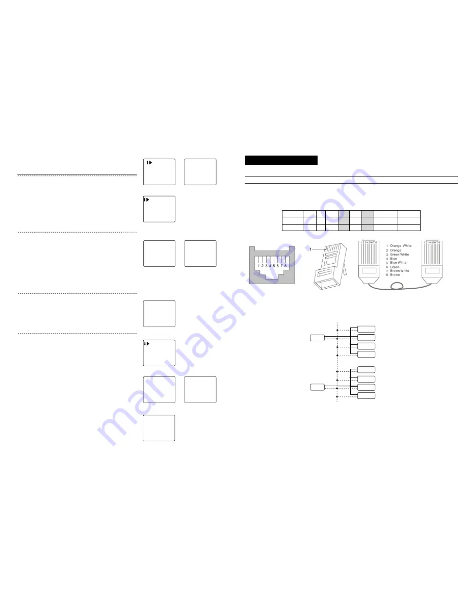
Connection explanation
1. C-5 cable connection explanation
All C-5 system use RJ45 connector, cable is in accordance with the international T568B standard, the order of wire from left to right is
orange white/ orange / green white/ blue/ blue white/ green/ brown white/ brown.
[Note] Please refer to Appendix4 for the plug-45 making method.
Pin No.
1
2
3
4
5
6
7
8
color
ORW OR GRW
BL
BLW
GR
BRW
BR
silk-screen
LA
LB
VF-
AF+
AF-
VF+
GND/COM1 DC+/COM2
2. UPS power supply connection explanation
When there are a lot of distributors used in the system and the sole gate way power supply can not load any more, some more power
supplies should be added to main line in the distributors.
[Notes] 1. When using one power supply for multiple distributors, the power supply is required to be connected to the middle distributor, the
position of power supply should be symmetry.
2. When the main line in the same building using multiple power supplies, the DC+ line should be disconnected between any two
adjacent power supplies, but GND line should be linked together.
3. When one power supply supports the building that is more than 6 floors, one RVV2X1.0 cable should be connected from DC+ and
GND of power supply to the DC+ and GND of each distributor. This is to avoid the line loss through the long distance transmission.
Distributor 8
Power
Power
DC+
GND
GND
DC+
GND
Distributor 7
Distributor 6
Distributor 5
Distributor 4
Distributor 3
Distributor 2
Distributor 1