


33
6. Product installation explanation
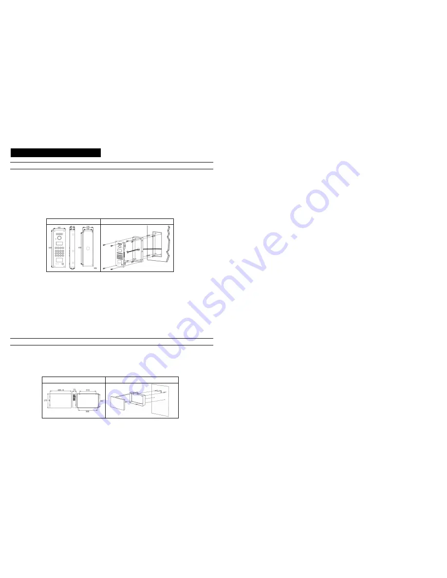
Door station installation
[Note] Picture for reference only, please refer to the m anual attached wi th door st ati on for detai led installati on .
Installation method
◆
1. Make a square groove on proper position on wall or door according to the dimension of door station.
2. Put the door station back cover into the groove, according to the hole on the cover to make marks in the groove, and then drill holes.
3. Insert plastic expanding pipes into the holes in the groove, then install the back cover to the square groove with screw.
4. Install the top parts of door station to the back cover, use screws to fasten it from the screw holes on the top part.
[Note] if the door station is installed on iron door, no need to proceed step 2 and 3, please directly weld the back cover into the groove of iron
door.
Dimension
Installation iconography
◆
Installation notes
①
When drill holes on iron door or wall, please remember to be in accordance with the specific model and installation dimension.
②
Before install the back cover of door station, please take care of the installation depth to ensure the surface of the door station is on
the same lever with the surface of iron door and wall in case there is big gap between the surface of door station and wall/iron door.
Flush installation type should be installed to the security door that is not to be opene
③
d
Do not install door station in the environment of rain, wet, high temperature, and too much ash. Don’t install it near to ca
④
usticity
objects.
⑤
Installation height: Above the ground for 1100mm-1400mm. (Suggestion: When using video door station, the camera’s view scope
should be considered for the installation height to proper see the visitors’ face. People in wheelchair’s height should be also
considered.)
UPS power supply installation
◆
Installation method
1.
Refer to the power supply dimension, mark the position of holes on back cover of power
supply on the wall, and insert 2/3
length of screw into the wall.
2. Hang the power supply back cover to the screw.
3. Fasten power supply box by using two screws from the inside of power supply back cover, then put on the power supply front cover.
Dimension
Installation iconography
22
Following setting especially for G9 door station (By remote control)
First , you must enter the system setting:
1.Press [FN] +password(4 bits) +[ENTER]
2.The door station will sound a long beep and the [DOOROPEN] LED will flash slowly. It means enter the system setting.
[Note] the original password is /1234/.
1. Memory/Information clearance
(Only used in the first time programming)
1. Press [FN] + [DEL+] +[ENTER]
2. The door station will sound a long beep. And the [DOOR OPEN] LED will start to flash slowly. It means successfully to clean the indoor
phone data.
3. Press [FN] + [CLEAR] +[ENTER]
4. The door station will sound a long beep. And the [DOOR OPEN] LED will start to flash slowly. It means successfully to clean the
gate-way data.
2. Door Station No. setting
1. Press [SERVICE] + [UNLOCK], input door station number [apartment number(4 bits) + gate-way port number(1 bits)]
2. The door station will sound a long beep. And the [DOOR OPEN] LED will start to flash slowly. It means successful.
3. Indoor phone setting
1. Press [FN]+[REG-], [DOOROPEN] LED will flash quickly.
2. Press [CALL] button on the door station, system will sound a short beep.
3. Input "Distributor (3 bits)" + "Port number (1 bits)" + [ENTER]
4. If the door station sounds a long beep, that means the program is successful. While the [DOOROPEN] LED will still flashing quickly.
The program for another buttons is available by repeating step 2 and step3.
4. Indoor phone data upload
[Note] This function is for upload indoor phone data saved in door station to gate-way when in network.
1. Press [FN] + [TIME] +[ENTER]
2. The door station will sound a long beep. And the [DOOR OPEN] LED will start to flash slowly. It means successfully to upload the
indoor phone data.
Step 3. Testing basic functions
To test and check each device whether they work properly or not.
1. Door station calling indoor phone
Press call button on door station, the corresponding indoor phone will ring, then answer the call and unlock the door.
Malfunction 1. Door station sounds three short “di”.
● Check the wiring between door station and gate
-way, distributor and gate-way
Malfunction 2. Door station enters ringing status, indoor phone doesn’t response.
●Check wiring between indoor phone and distributor.
2. Accessory door station calling indoor phone(only for system with accessory door station)
Press call button on door station to call indoor phone, indoor phone answers and unlocks the door.
The problem phenomenon and solving method of the accessory door station is the same with the door station
3. Indoor phone surveillance (only for video system)
Press monitor button on indoor phone to monitor the door station.