-
30
-
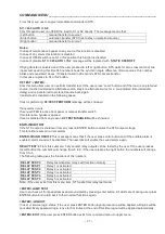
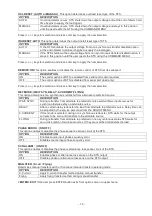
NEW PASS:0000
left and right keys moves the blinking digit to either left or right. Use up and down keys to
change the blinking number. After you typed all 4 numbers press enter button.
ENTER:OK >:EXIT
this message means that if the user presses enter button the new password is valid from
now on. The user can exit from this message by pressing the right button.
In case of forgot the service password, connect the jumper JP2 on the main board this will activate the
service login mode you can access to ADJUST MENU.
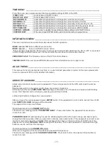
USER PASSWORD ________________________________________________________
User password is 4 characters length ,these are numeric characters .
At first entry to this menu
USR.PASS: 0000
message is showned ,one of characters is replaced with blinking
cursor ,this character can be change by pressing up and down buttons.
Left and right buttons changes the cursor position.
After you typed the user password press
ENTER
button ,if the password is correct at the second line of LCD
panel
USER LOGIN
message will be showned.
User password can be change by the users during login status.
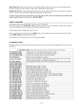
ALARM MESSAGES
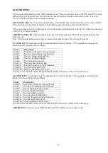
Following table shows all the alarm messages which are used in STS and these messages will be recorded in
events log.
2. LINE MESSAGES
(these messages are shown on the second line of LCD panel)
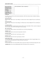
A1 SOURCE 1 BAD
If input source 1 is out of tolerance this alarm occurs
A2 SOURCE 2 BAD
If input source 2 is out of tolerance this alarm occurs
A3 SYNCHRON BAD
Shows that 2 input sources are not synchronized
A4 OVERLOAD
Output current of the STS is too high
A5 NSYNC.INHIBIT
Non synchronous transfer is disabled by the user, and during non sync status
transfer process started ,currently output shutdowns
A6 XFER INHIBIT
During transfer the STS can not find a good source and the output shutdowns
A7 OUT.BAD ON S1
A8 OUT.BAD ON S2
A9 PSP FAILURE 1
Redundant power supply 1 is bad
A10PSP FAILURE 2
Redundant power supply 2 is bad
A11 OVERTEMP
SCR heatsink temperature is too high
A12 MAN.XFER S1
Load is transferred to Source 1 by the user
A13 MAN.XFER S2
Load is transferred to Source 2 by the user
A14 BYPASS TO S1
Load is directly transferred to Source 1 by maintenance bypass
A15 BYPASS TO S2
Load is directly transferred to Source 2 by maintenance bypass
A16 OUTP.SW.OFF
The output switch of the STS is off
A17 INP.SW.1 OFF
The Source 1 input switch is off
A18 INP.SW.2 OFF
The Source 2 input switch is off
A19 S1 BLACKOUT
On Source 1 input black out sensed
A20 S2 BLACKOUT
On Source 2 input black out sensed
A21 S1 FRE.FAULT
Source 1 input frequency out of tolerant
A22 S2 FRE.FAULT
Source 2 input frequency out of tolerant
A23 S1 BAL.BAD
Source 1 input phase balance bad
A24 S2 BAL.BAD
Source 2 input phase balance bad
A25 ROTATE S1 Ph
Source 1 input phase sequence is BAD
A26 ROTATE S2 Ph
Source 2 input phase sequence is BAD
A27 SHORT CIRCUIT
Short circuit status fixed on the output of the STS
A28 MISFUNCTION
Faulty usage of manual transfer switch
A29 BACKFD.TRIP1
Backfeed protection activated for source 1
A30 BACKFD.TRIP2
Backfeed protection activated for source 2
Содержание InfoSTS
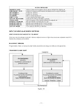
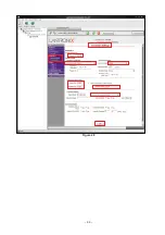
Страница 45: ...44 Figure 28...
Страница 47: ...NOTES...

