


-
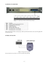
4
-
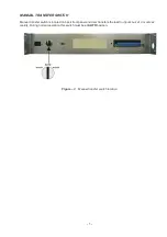
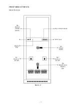
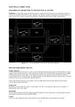
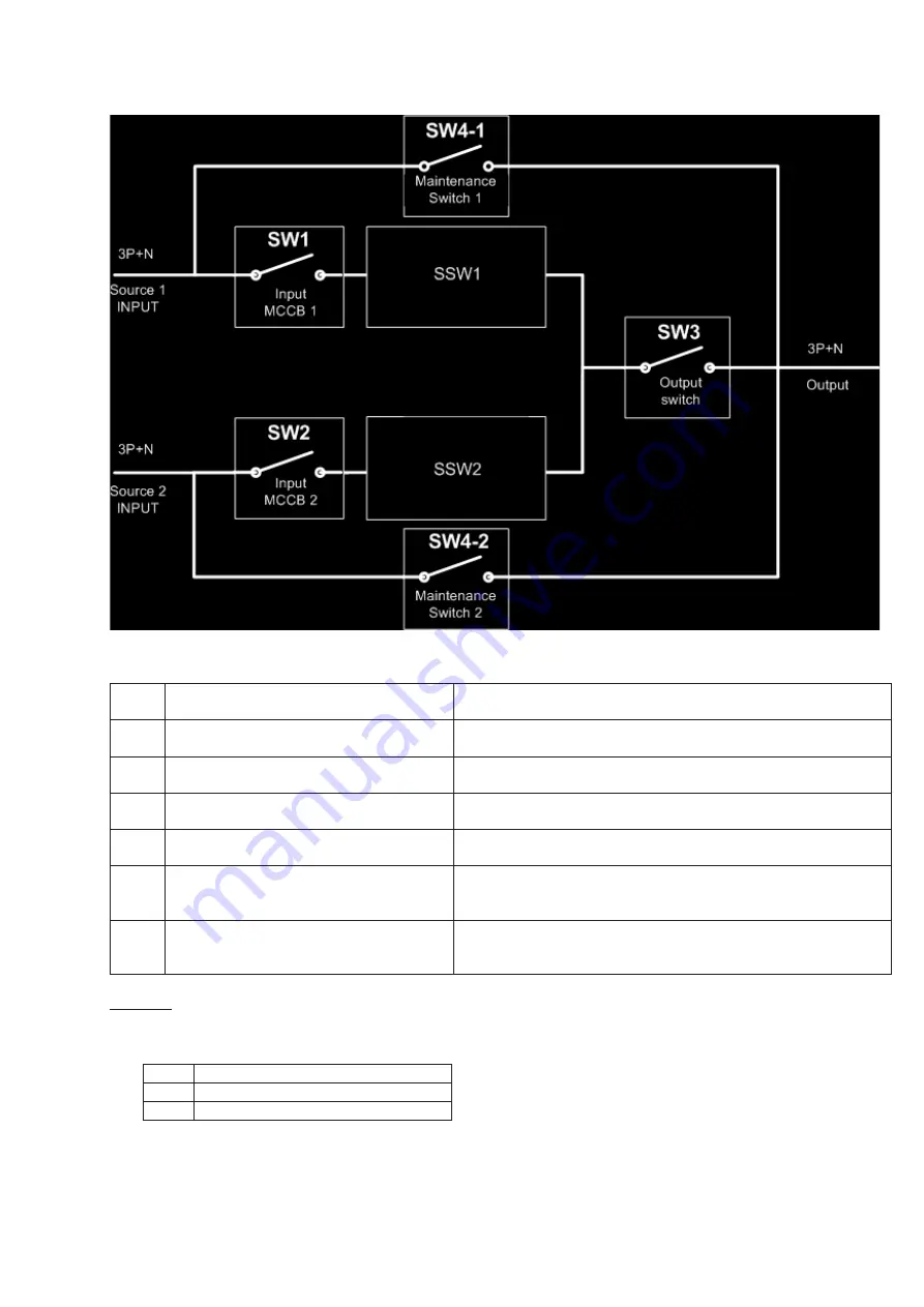
BLOCK DIAGRAM OF THE STS
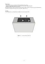
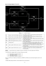
Figure – 2
STS Block diagram
S1
Source 1 input circuit breaker (MCCB)
This switch is thermal and magnetic protected type and
shutdowns source 1 input
S2
Source 2 input circuit breaker (MCCB)
This switch is thermal and magnetic protected type and
shutdowns source 1 input
S4-1
Mechanical bypass switch to source 1
During maintenance these contacts connect Source 1 input
to STS output directly
S4-2
Mechanical bypass switch to source 2
During maintenance these contacts connect Source 2 input
to STS output directly
S3
Output switch
This switch shutdowns the output voltage of STS . During
maintenance the position of this switch must be OFF.
SS1
Static transfer SCR circuit to source 1
This static switch contains SCRS and snubber components
and driven by a driver circuit which is controlled by the
microprocessor.
SS2
Static transfer SCR circuit to source 2
This static switch contains SCRS and snubber components
and driven by a driver circuit which is controlled by the
microprocessor.
NOTE :
Figure 2 shows only 1 phase of 3 phase construction. The other phases are not shown.
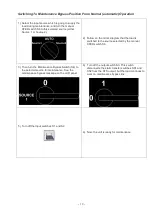
The maintenance bypass switch is a 3 pole change-over switch
1
Maintenance bypass to source1
0
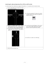
Automatic operation
2
Maintenance bypass to source2
Source 1 and Source 2 input circuit breakers are MCCB’s with thermal overload and magnetic short circuit
releases.
A Manual Static Bypass Switch is also available for easy load transfer.
Содержание InfoSTS
Страница 45: ...44 Figure 28...
Страница 47: ...NOTES...


