User Guide
49 of 67
002-32601 Rev. *C
2021-12-02
EZ-
PD™ PMG1 MCU prototyping kits guide
CY7110/CY7111/CY7112/CY7113
Application development o
n CY711x kits using ModusToolbox™ software
The
Console
tab displays the progress of the build/program. You can check the
Problems
tab for any errors
and warnings. The success message is displayed on the Console tab if the programming is successfully
completed.
5.3.2
Debugging using ModusToolbox™ software
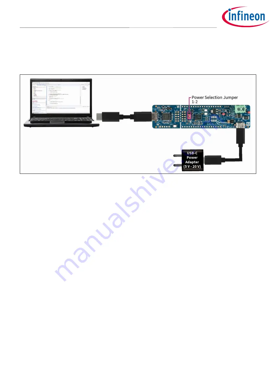
Figure 42
Debugging though KitProg3
Do the following to debug an application on the CY7111, CY7112, and CY7113 prototyping kits over the KitProg3
interface using the Eclipse IDE for ModusToolbox
™ software
.
1.
Open the Eclipse IDE for ModusToolbox
™ software
on the host PC and select the PMG1 project. For details,
see the Eclipse IDE for Mo
dusToolbox™ software
user guide
2.
Place the jumper shunt on pins 1
–
2 of the power section jumper (J5) to configure the kit in operational
mode.
3.
Connect the USB PD sink port to the USB PD source to activate the onboard LDO, Load switch, and user LED.
Ensure that LED4, which is the power LED, glows green.
4.
Connect the kit to the host PC through programming KitProg3 USB Type-C port. Ensure that LED1 and LED2
glow amber. LED2, which is KitProg3 Power LED, indicates that the KitProg3 module is powered. LED1,
which is the status LED, indicates the programming/debug mode and status, and is ON when KitProg3 is
powered.
5.
On the
Quick Panel
, click
<Application name> Debug (KitProg3_MiniProg4)
from the
Launches
section.
The IDE will switch to debugging mode and will halt at the first line of the main function. This indicates that the
application is ready for debugging.
Do the following to debug an application on the CY7110 prototyping kits over the KitProg3 interface using the
Eclipse IDE for ModusToolbox
™ software
.
1.
Open the Eclipse IDE for ModusToolbox
™ software
and select the
PMG1
project on the host PC. For details,
see the Eclipse IDE
for ModusToolbox™ software
user guide
2.
Place the power selection jumper (J5) shunt on pins 2
–
3 of the power selection jumper (J5) to enable
ModusToolbox
™ software
to acquire the target (EZ-
PD™
PMG1-S0 MCU) in power cycle mode.
3.
Connect the USB PD sink port to the USB PD source to activate onboard LDO, Load switch, and user LED.
Ensure that LED4 glows green.


