NAME and F
U
N
C
T
IO
N
2
2.1 Camera and Viewfi nder
19
HDK-790GX 1403 VER1 (U)
⑥
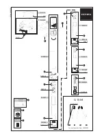
Q-TV/GL IN and MON OUT connector
A connector used to output the selected signals using the Q-TV/GL IN and MON OUT selector switch.
- When it is set to “Q-TV/GL”
Changes the analog video signal that is input into the Q-TV connector on the back of CCU to the Q-TV signal (video trunk
input) for the monitor to output. The Q-TV signal output function is supported only during the CCU operation.
It inputs the PS/S signal (tri-level sync signal) as an external sync signal (genlock input). The external sync signal input is
supported only during the self-contained operation.
- When it is set to “MON OUT”
Outputs the monitor signal. Select the MON and SYNC signals from the camera menu.
⑦
MONI-SDI OUT connector
A connector used to output the HD SDI signal.
Select the VF, MAIN, RETURN, and HD Q-TV signals from the camera menu.
⑧
QTV-2 connector
A connector used to output the QTV-2 signal.
⑨
HD TRUNK IN connector
A connector used to input the HD TRUNK signal (1.5G-SDI).
The input 1.5G-SDI signal can be output from the connector on the back of CCU.
Caution:
The HD TRUNK output for the CCU-970 is optional.
⑩
REMOTE connector
A connector used to connect the various remote control panels (OCP, MCP, RCP) and communicate the various control signals
during the self-contained operation.
⑪
I/O connector
A multi-connector that includes the GREEN/RED TALLY control output signal, RET-1 and RET-2 control input signals, and RS-
422 data control signal, etc.
⑫
MIC POWER switch (option)
A switch to change the power supply for the microphone that is connected to the MIC-1and MIC-2 connectors.
Select it depending on the type of microphone to be used.
AB+12V : Supplies power to the microphone for +12V AB power.
OFF
: Does not supply power to the microphone. If the dynamic microphone or microphone includes a built-in power supply
and does not require power supply, use it in this position.
+48V
: Su48 V phantom power to the microphone.
Содержание HDK-790GX
Страница 1: ...HIGH DEFINITION CAMERA SYSTEM HDK 790GX OPERATION MANUAL...
Страница 2: ......
Страница 17: ...1 OUTLINE OUTLINE...
Страница 18: ...HDK 790GX 1403 VER1 U...
Страница 24: ...8 HDK 790GX 1403 VER1 U 1 2 Operating Systems...
Страница 26: ......
Страница 27: ...2 NAME and FUNCTION NAME and FUNCTION...
Страница 28: ...HDK 790GX 1403 VER1 U...
Страница 43: ...3 INSTALLATION INSTALLATION and CONNECTION and CONNECTION...
Страница 44: ...HDK 790GX 1403 VER1 U...
Страница 46: ...3 1 Preparation 30 HDK 790GX 1403 VER1 U...
Страница 48: ......
Страница 59: ...4 OPERATION OPERATION...
Страница 60: ...HDK 790GX 1403 VER1 U...
Страница 75: ...5 CAMERA SETTINGS CAMERA SETTINGS and ADJUSTMENT and ADJUSTMENT...
Страница 76: ...HDK 790GX 1403 VER1 U...
Страница 98: ...86 HDK 790GX 1403 VER1 U 5 3 Using the Memory Card...
Страница 99: ...6 TROUBLE SHOOTING TROUBLE SHOOTING and MAINTENANCE and MAINTENANCE...
Страница 100: ...HDK 790GX 1403 VER1 U...
Страница 110: ...98 HDK 790GX 1403 VER1 U 6 6 Replace the fuse...
Страница 111: ...7 SPECIFICATIONS SPECIFICATIONS...
Страница 112: ...HDK 790GX 1403 VER1 U...
Страница 116: ...104 HDK 790GX 1403 VER1 U 7 2 External Dimensions Diagram Left Side View 70 453 3 12 398 5...
Страница 132: ...HDK 790GX 1403 VER1 U...
Страница 134: ......
Страница 135: ......


