


The information contained in this document is the property of Automatic Systems and is confidential. The recipient shall refrain from using it for any purpose other than the use of the products or the
execution of the project to which it refers, and from communicating it to third parties without Automatic Systems’ prior written agreement. Document subject to change without notice.
BL3x-MT-EN-08
page
47/59
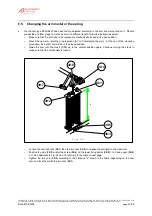
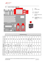
6.5.
Changing the arm model or the spring
•
Your barrier type BL32/BL33 has been factory-adjusted according to the arm boom mounted on it. Should
you decide at a later stage to mount an arm of a different length, follow the instructions below.
--
Make sure that the arm tube to be replaced is mechanically locked in its open position.
--
Mount the new arm referring to
paragraphs [5.3 to 5.5Installing the arm]
. At the end of the mounting
procedure, the barrier arm will be in the closed position.
--
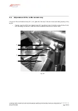
Raise the arm with the crank (
1:10
) up to the vertical position again. Continue turning the crank to
make sure that the mechanism is locked.
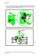
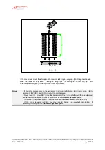
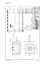
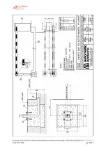
30:3
Fig. 30
30:4
30:1
30:2
x
30:6
30:7
30:5
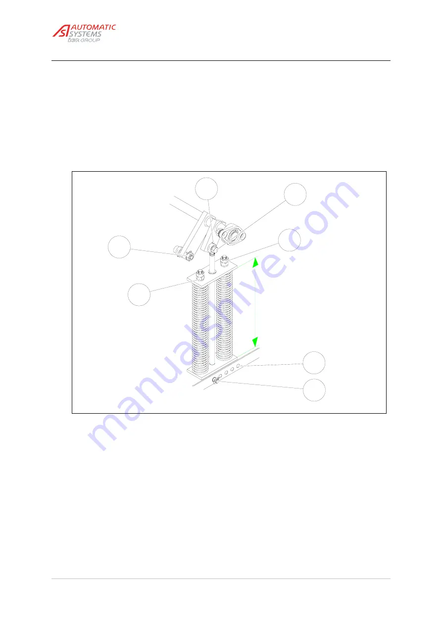
--
Loosen the two lock nuts (
30:1
) then the two nuts (
30:2
) to release the spring(s) to the maximum.
--
Position the axle (
30:3
) and/or the screw (
30:4
) on the lower fixing points (
30:5
)
1
to
5
and upper (
30:6
)
a
or
b
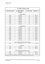
as illustrated in Fig. 30 and 31, referring to the table on next page.
--
Tighten the two nuts (
30:2
) according to the distance "x" shown in the table, depending on the new
arm, and lock them with the two nuts (
30:1
).


