The information contained in this document is the property of Automatic Systems and is confidential. The recipient shall refrain from using it for any purpose other than the use of the products or the
execution of the project to which it refers, and from communicating it to third parties without Automatic Systems’ prior written agreement. Document subject to change without notice.
BL3x-MT-EN-08
page
34/59
5.6.
Fixing the shrouds (BL32 only)
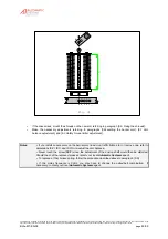
Fig. 13
13:2
13:1
13:3
13:4
13:5
13:8
13:6
13:7
13:6
13:7
13:9
13:10
13:11
Attention
:
Fixing the shrouds requires two people!
•
Shrouds need to be installed for an arm boom from 7.01m (6.01m in case an option if fixed to the arm). The
stainless steel bracing wires (
13:1
) are factory-fixed with the collar (
13:2
) on the arm.
•
When the three arm segments are fixed and secured to one another (see
paragraphs 4.3
and
4.4
), proceed
as follows:
--
Unroll the cable (
13:1
) and pass it onto the upper screw of the collar (
13:2
), not forgetting to place the
eyelet.
--
Loosen the strainers (
13:3
) at maximum length.
--
Remove the security pin (
13:4
) and the axle (
13:5
) from the strainers.
--
Position the strainer (
13:3
) onto the wing (
13:6
) of the stretcher plates (
13:7
).
--
Insert the axle (
13:5
) into the wing of the stretcher plate and fix the security pin (
13:4
) again.
--
Tighten the strainers (
13:3
) so as to make the arm vertical in its open position and horizontal in its
closed position. If the precise positioning of the arm is not possible, see
paragraph 4.8.
Note:
The figure above shows a two-stretcher assembly. Proceed likewise for a single-stretcher
assembly (lateral arm).


