The information contained in this document is the property of Automatic Systems and is confidential. The recipient shall refrain from using it for any purpose other than the use of the products or the
execution of the project to which it refers, and from communicating it to third parties without Automatic Systems’ prior written agreement. Document subject to change without notice.
BL3x-MT-EN-08
page
12/59
3.2. Example
2
•
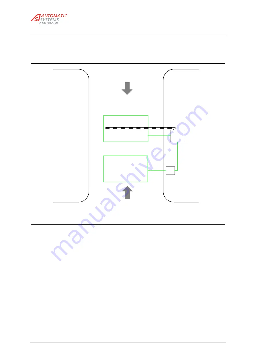
The figure below shows an example of bi-directional access. The barrier opening is controlled in both
directions.
Fig. 7
Closing loop
Exit
BL
Entry
P
Opening loop
This illustration applies to left-hand driving. For right-
hand driving, the configuration changes accordingly.
•
The barrier opening at entry is controlled by a peripheral P (e.g. a card reader) operated by a detection loop
embedded in the road surface. Opening the barrier is impossible if no vehicle is present on the loop, even
though a valid card is inserted in the reader.
•
The opening manoeuvre at exit is manually operated by the attendant via a single-push button box.
•
Closing and stop are automatically assured by the vehicle detection loop connected to the barrier and
embedded in the road surface under the arm boom.
•
The equipment is controlled by the control board.
•
For the exact model to install, as for the correct choice of loops to use (depending on the road width, etc.),
please refer to the corresponding technical data sheets or contact your local Automatic Systems agent.


