


The information contained in this document is the property of Automatic Systems and is confidential. The recipient shall refrain from using it for any purpose other than the use of the products or the
execution of the project to which it refers, and from communicating it to third parties without Automatic Systems’ prior written agreement. Document subject to change without notice.
BL3x-MT-EN-08
page
41/59
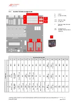
6. ADJUSTMENTS AND TECHNICAL INTERVENTIONS
WARNING!
REMINDER:
Y
OUR RISING BARRIER TYPE
BL32/BL33
COMPRISES A MECHANISM AND VARIOUS ELECTRICAL COMPONENTS
.
A
NY NEGLIGENCE DURING AN INTERVENTION IN THE MACHINE MAY SERIOUSLY ENDANGER YOUR SAFETY
.
A
S SOON AS YOU
OPEN THE HOUSING
,
SWITCH OFF THE CIRCUIT BREAKER
(
4:1
)
LOCATED BEHIND THE SIDE DOOR
.
B
E CAREFUL IN HANDLING
ANY INTERNAL ELEMENT WHICH MIGHT BE UNDER POWER OR COULD BE SET IN MOTION
.
T
HE HOOD SHOULD BE REMOVED ONLY IF YOU NEED TO REPLACE THE DRIVING SHAFT OR A SPRING
,
ADJUST THE BELT
(
S
)
OR
PROCEED WITH THE MAINTENANCE
.
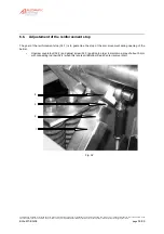
6.1.
Arm balance adjustment
•
The power needed to set the mechanism in motion is minimal due to the built-in compression spring(s). To
operate properly, the tension of the spring(s) must be correctly adjusted, i.e. the strength needed to activate
the mechanism must be equal in either direction. If necessary, proceed with the adjustment as follows:
--
Insert the crank handle (
1:10
) into the crank hole and turn it in either direction to unlock the arm and
bring it to an angle of approx. 20° (+ refer to "safety warnings" chapter!).
--
Uncouple the torque limiter by loosening the 8 lock nuts (
26:1
) and the 8 screws (
26:2
) without
removing them.
--
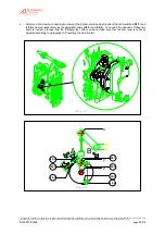
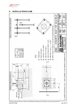
Move the barrier arm manually to an angle of 45°.
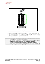
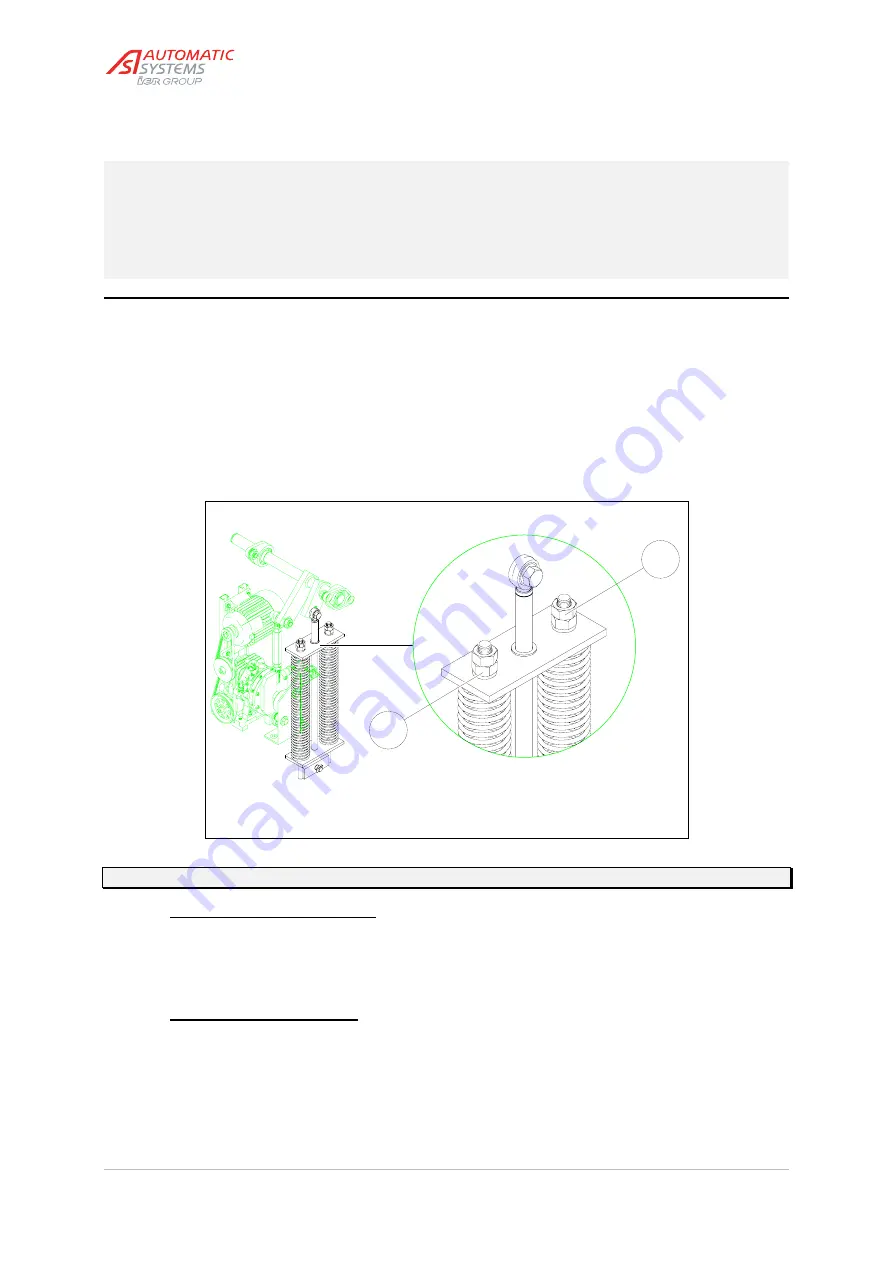
100
23:2
Fig. 23
23:1
Note:The figure above shows a double spring assembly. Proceed likewise for a single or triple spring assembly.
a) If the arm moves downwards:
)
Loosen the two lock nuts (
23:1
).
)
Tighten the two nuts (
23:2
) smoothly and equally to compress the spring(s) harder and position
the arm at 45°.
)
When the desired result is obtained, tighten the two nuts (
23:1
) again to block the nuts (
23:2
).
b) If the arm moves upwards:
)
Loosen the two lock nuts (
23:1
).
)
Loosen the two nuts (
23:2
) smoothly and equally to release the compression spring(s) and
position the arm at 45°.
)
When the desired result is obtained, tighten the two nuts (
23:1
) again to block the nuts (
23:2
).
•
Check the V-belt(s) following the instructions of
paragraph [5.2. Belt tension adjustment]
, then adjust the
safety clutch referring to
paragraph [5.3. Safety torque limiter adjustment]
.


