10
Concord CXA/H
- Installation and Servicing
INSTALLATION
7
PACKAGING AND BOILER REMOVAL
1.
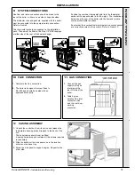
Remove the casing carton and outer packaging
frame.
2.
Remove the casing pack support frame.
3.
Remove the distributor tube pack, controls package
and installation pack.
4.
Remove the 2" BSP steel handling bars from the
installation pack.
5.
Remove the 4 base bolts holding assembly to the
packaging base.
6.
Remove the wood screws securing the front cross
member on the packaging base.
7.
Remove the gas cock by unscrewing the union and
screw in the handling bars into the 2 front tappings.
Protect the exposed inlet gas union from ingress of
dirt.
8.
Knock out the front spacing blocks from the packaging
base, ensuring that the boiler assembly is supported,
using 2" BSP handling bars.
9.
Using the handling bars, manoeuvre the boiler forwards
on the packaging base and slide over collapsing base on
to the floor.
Note.
Before manoeuvring the boiler into its final position
see Frame
8
c.
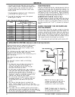
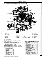
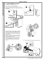
Fit the 2 thermostat pockets. Refer to Frame 9.
Note.
Frame 9 shows the relationship between
the overheat thermostat and the flow tapping.
d.
Complete the water connections by plugging the
2 front top tappings with the 2" BSP plugs
provided.
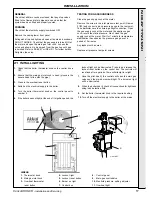
1.
Fit the distributor tube (supplied with the boiler) into
one of the return connection. That is one of the rear
lower ports - refer to Frame 5.
Fit the flange, using the M10 x 35mm screws and
washers provided.
Ensure that the notch in the tube flange sits correctly
into the groove on the section and that the 2 sealing
gaskets are correctly assembled on the tube.
2.
Fit the 1" tapped flange to the other lower rear
connection, using the gasket and M10 x 25mm
screws and washers provided.
3.
Temporarily screw the 2 handling bars (2" pipe) into
the top tappings and manoeuvre the boiler into
position.
4.
Complete the system connections, using suitable
jointing compound, as follows:
a.
The flow connection may be made to either of the
rear top tappings (either at the same side as the
return or opposite the return).
To avoid air locks, any reduction in pipe size must
be made in the vertical plane or achieved by using
eccentric bushes.
b.
The 1" tapping in the redundant return flange may
be used for the cold feed on an open system or
connection of a pressure vessel if on a sealed
system.
If not required for this purpose it should be
plugged.
8
BOILER ASSEMBLY
INST
ALLA
TION
Содержание Concord CXA 40/H
Страница 1: ......


