Concord CXA/H -
Installation and Servicing
21
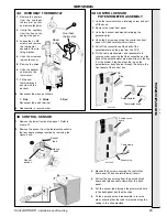
SERVICING
1.
Remove the LH burner as previously described in
Frame 27
2.
Remove the 2 screws securing the control box front
panel, lift it and carefully lower it.
3.
Remove the spark lead and flame detector lead
connection from the S4561B1054 PCB in the control
box. Undo the strain relief clamp and pass the sleeved
wires through the grommetted hole in the back panel.
4.
Remove the spark electrode by undoing the back nut.
5.
Fit the new electrode and reassemble in reverse order,
ensuring that the spark electrode lead passes through
the sleeving and that the sleeving passes through the
strain relief clamp in the control box before retightening.
Ensure that the push-on connections are as follows
(from left to right): spark electrode, blank, earth, flame
detector.
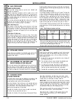
31 SPARK ELECTRODE AND LEAD
33 GAS CONTROL VALVE
1.
Undo the pilot gas pipe connection at the gas control
valve (if required).
2.
Undo the screw securing the electrical plugs on the
gas valve and lift them off.
4.
Check that the gas inlet cock is OFF, unscrew the 4
screws from the inlet flange, and the 4 screws from
the outlet flange and remove the valve.
(CXA 90/H-120/H, loosen the other 4 screws on the
inlet flange securing the other gas valve).
5.
Replace the gas control valve and re-assemble in
reverse order, ensuring that the arrow indicating the
direction of flow is in the correct position.
6.
Ensure that a new ‘O’ ring seal is correctly placed in
each flange connection.
7.
Test for gas soundness.
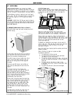
34 MAIN BURNERS
1.
Remove the NOx duct and burner front plate, as
previously described in Frame 27.
2.
Both RH and centre burners can be removed by sliding
each one back to clear the injector, and then lifting out.
3.
To exchange the LH burner remove it from the boiler as
previously described in Frame 27. Remove pilot burner
as described in Frame 30.
4.
Fit new LH burner and the centre and RH burners.
Note.
Ensure that the pilot burner is correctly fitted, i.e.
facing the front, and that the pilot injector has not been
omitted.
7.
Reconnect the pilot gas pipe connection to the gas valve.
IMPORTANT.
Care must be taken to prevent damage to the
combustion chamber insulation when replacing burners.
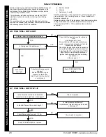
1.
Remove the LH burner as previously described in Frame 27
2.
Pull off the lead at the electrode and unscrew the flame detector
electrode.
3.
Fit the new electrode and reassemble in reverse order.
4.
To change the lead, remove the 2 screws securing the control
box front panel, lift it and carefully lower it. Remove the flame
detector lead and spark lead connection from the S4561B1054
PCB in the control box, undo the strain relief clamp and pass
the sleeved wires through the grommeted hole in the back
panel.
5.
Pull the lead through the sleeving. The new lead must be
passed through the sleeving small fitting first.
6.
Reassemble in reverse order, ensuring that the sleeving
passes through the strain relief clamp before tightening.
Ensure that the push-on connections are as follows (from left to
right): spark electrode, blank, earth, flame detector.
32 FLAME DETECTOR AND LEAD
Pilot burner
Fixing screw (2)
LH burner
Flame
detector
electrode
Spark
electrode
Backnut
Flame detector
lead
Pilot draught shield (
not fitted to CXA 120/H
)
Pilot burner
Fixing screw (2)
LH burner
Flame
detector
electrode
Spark
electrode
Backnut
Flame detector
lead
Pilot draught shield (
not fitted to CXA 120/H
)
SER
VICING
Содержание Concord CXA 40/H
Страница 1: ......

