background image

Concord CXA/H - 

Installation and Servicing

31

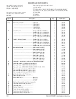
SHORT LIST OF PARTS

Key No.

Description

Qty.

Product No.

48

Right hand casing side panel - white stove enamel .. CXA 40/H

1

111 650

..................................................................................... CXA 50/H

1

111  651

..................................................................................... CXA 60/H

1

111  651

..................................................................................... CXA 70/H

1

111  652

..................................................................................... CXA 80/H

1

111  652

..................................................................................... CXA 90/100/H

1

111  653

..................................................................................... CXA 110/120/H

1

154  898

49

Left hand casing side panel - white stove enamel ..... CXA 40/H

1

111 650

..................................................................................... CXA 50/H

1

111  651

..................................................................................... CXA 60/H

1

111  651

..................................................................................... CXA 70/H

1

111  652

..................................................................................... CXA 80/H

1

111  652

..................................................................................... CXA 90/100/H

1

111  653

..................................................................................... CXA 110/120/H

1

154  898

50

Casing top panel - white stove enamel ...................... CXA 40/H

1

111 293

..................................................................................... CXA 50/H

1

111  294

..................................................................................... CXA 60/H

1

111  295

..................................................................................... CXA 70/H

1

111  296

..................................................................................... CXA 80/H

1

111  297

..................................................................................... CXA 90/100/H

1

111  298

..................................................................................... CXA 110/120/H

1

154  897

51

Casing lower front panel - white stove enamel c/w lighting instructions

1

171 842

52

Casing upper front control panel (less controls) ........

1

154 846

53

Casing assembly,  complete - white stove enamel .... CXA  40/H

1

157 389

..................................................................................... CXA  50 /H

1

157  390

..................................................................................... CXA  60/H

1

157  391

..................................................................................... CXA  70/H

1

157  392

..................................................................................... CXA  80/H

1

  157  393

..................................................................................... CXA 90/100/H

1

157  394

..................................................................................... CXA 110/120/H

1

157  395

55

Reset Switch Assembly ...............................................

1

155 269

Содержание Concord CXA 40/H

Страница 1: ......

Страница 2: ...1078 Water content litre 22 30 30 37 37 45 45 53 53 gal 4 8 6 6 6 6 8 2 8 2 9 9 9 9 11 7 11 7 Table 2 General Data This value is in the UK government s Standard Assessment Procedure SAP for energy ra...

Страница 3: ...he law is complied with The Concord CXA 40 H 120 H range of boilers has been tested and certified by British Gas to prEN656 for use with Natural gas only Multiple boiler installations The Concord CXA...

Страница 4: ...is designed to protect the boiler and may not necessarily protect the remote parts of the system OPTION KITS Remote indication kit This kit gives the facility of remote indication of the boiler statu...

Страница 5: ...rrun litres Relationship between load and water volume for the minimum capacity of water circuit during the 6 minute pump overrun period for different boiler outputs Graph 1 Heat Load Water Volume CXA...

Страница 6: ...into the expansion cistern must be avoided The above circuit capacity during pump overrun may be achieved either by provision of an adequate bypass circuit or by ensuring that a zone of suitable size...

Страница 7: ...2 BS 6281 Part 1 BS 6282 Part 1 BS 6283 Part 4 Working pressure 6 bar maximum Particular reference should be made to BS 6644 Section 6 and Guidance note PM5 Automatically controlled steam and hot wate...

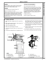
Страница 8: ...less steel rigid or flexible flue liner grade 304 316 may be used in conjunction with a 50 mm minimum thick layer of vemiculite or perlite granules between the liner and the inner skin of the chimney...

Страница 9: ...ssembled boiler body with distributor tube on a wooden pallet base enclosed in a wooden crate 2 Carton containing the casing fastenings and flue brush 3 Carton containing the installation pack and ins...

Страница 10: ...and the flow tapping d Complete the water connections by plugging the 2 front top tappings with the 2 BSP plugs provided 1 Fit the distributor tube supplied with the boiler into one of the return conn...

Страница 11: ...stat phial and control sensor are correctly secured in the pockets Refer to Frame 13 9 SYSTEM CONNECTIONS One flow and return connection should be made to the rear of the boiler either on one side or...

Страница 12: ...stat pocket adjacent to the flow connection Fit the plastic Heyco bush over the sensor lead at the line shown and insert it into the thermostat pocket Ensure that the Heyco bush is correctly located 1...

Страница 13: ...unswitched live supply which the boiler requires to allow the pump overrun facility to operate should be controlled by the above switched fused supply but should connect from there directly to the boi...

Страница 14: ...14 Concord CXA H Installation and Servicing INSTALLATION 16 INTERNAL WIRING br brown r red LEGEND b blue bk black y yellow w white y g yellow green or orange v violet pk pink INSTALLATION...

Страница 15: ...any zone may be the load during overrun all zones MUST individually be able to satisfy the conditions in the foregoing paragraph If not all zones can do this then consider other means of control deta...

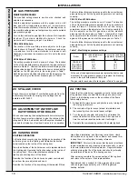
Страница 16: ...now calls for heat its thermostat will open Zone 1 valve via the normally open contacts of the relay IMPORTANT Terminal L2 may control the appropriate pump s directly provided that the total running...

Страница 17: ...2 minutes Any leaks must be cured Replace all pressure test point screws 21 INITIAL LIGHTING 1 Check that the boiler thermostat knob on the control box is OFF 2 Ensure that the main gas inlet cock is...

Страница 18: ...ectly to manual on off operations of any controls fitted in the gas control circuit Check in the following manner the operation of the flame failure safety device 1 Extinguish the main burner and pilo...

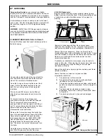
Страница 19: ...door lift it and carefully drop it down Pull off the flame detector lead and the spark electrode lead connections from the S4561B1054 PCB the left hand board Undo the strain relief clamp and feed the...

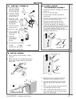
Страница 20: ...on the inside of the casing front panel and check the gas connections for tightness as detailed under Testing for Gas Soundness Frame 20 Check gas pressures and the gas rate test as instructed in Fra...

Страница 21: ...Frame 27 2 Both RH and centre burners can be removed by sliding each one back to clear the injector and then lifting out 3 To exchange the LH burner remove it from the boiler as previously described...

Страница 22: ...35 BURNER AND CONTROLS ASSEMBLY Exploded View CXA 40 H 80 H 36 BURNER AND CONTROLS ASSEMBLY Exploded View CXA 90 H 120 H LEGEND 1 Main gas inlet cock 2 Gas inlet union 3 Gas control valves 4 O ring s...

Страница 23: ...uit board and release cable clamp from the back panel 5 Pull the sensor lead through the grommeted hole in the back panel and the wire clips 6 Fit the new sensor and reassemble in reverse order ensuri...

Страница 24: ...he lower front panel 2 Undo the 2 screws securing the control box front panel Carefully lift it up and lower down 3 Pull off the 2 plugs and 3 push on connections from the board The board can now be r...

Страница 25: ...e part Gloves supplied with the spare part 1 Damp down the combustion chamber area containing the insulation boards 2 Remove the insulation boards The replacement boards are supplied in a plastic bag...

Страница 26: ...remove the left hand burner the pilot gas pipe connection at the gas valve must be removed 4 The left hand burner may now be removed by pushing it back to clear the injector and lifting it out taking...

Страница 27: ...bly are not fixed together therefore CARE MUST BE TAKEN TO PREVENT the installed section coming apart 8 Repeat the above procedure for all of the remaining sections until the assembly is complete 9 Fi...

Страница 28: ...sk which has required the breaking and remaking of electrical connections the following checks MUST be repeated Check that the gap between the electrode and pilot burner is 3 4 mm Ensure that the H T...

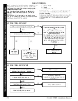
Страница 29: ...OES OUT ON OVERHEAT THERMOSTAT Are the thermostat sensors in their correct pockets YES Is there an unswitched live supply to terminal L1 on the plug in terminal connection at the control box Is the pu...

Страница 30: ...ctor 1 077 105 28 Pilot burner injector HONEYWELL 45900421 011 1 004 545 29 Gas control valve HONEYWELL V4601 AB 1034 1 154 810 Gas control valve HONEYWELL VR4605 AB 1019 CXA 90 120 H 1 111 869 Gas va...

Страница 31: ...2 CXA 80 H 1 111 652 CXA 90 100 H 1 111 653 CXA 110 120 H 1 154 898 50 Casing top panel white stove enamel CXA 40 H 1 111 293 CXA 50 H 1 111 294 CXA 60 H 1 111 295 CXA 70 H 1 111 296 CXA 80 H 1 111 29...

Страница 32: ...inuing improvement in the design and performance of its products The right is therefore reserved to vary specification without notice The Ideal Boilers Technical Training Centre offers a series of fir...

Отзывы: