IMM 8001/8002 – Digital Motor Protection Relay
ICE / CEE
____________________________________________________________________________________________
IMU307-1 GB Ind. B
78
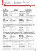
TESTS : Verification of the protection AGAINST MINIMUM LOADS (PUMP UNPRIMING) [37I]
CONNECTION, COEFFICIENT OF CORRECTION
Protection verification
Current injection
Coefficient
M
to be applied
Terminals
In =
1A
In =
5A
- single-phase
1.732
2-4 or 10-12
3-5 or 11-13
- balanced three-phase
1
2-4 phase 1
3-5 phase 1
10-12 phase 3
11-13 phase 3
Caution – the adjustment of coefficient K must be taken into account in the current to be injected :
K = In machine/IN
CT
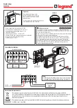
Sequence of operations to be performed
Results to be obtained
To simulate motor operation, it is required to instantaneously apply an Ipos current
equal to at least 1.5 In (start), then to decrease the Ipos current to a value
close to
In
(normal operation).
or Simulate motor operation by ap24V to the EL1 input (wire between
terminals A3 and B18).
On start, enabling time-delay tI>on is started. When it is ended, function [37I] is put
into serviced.
Check of undercurrent unit
Check of operating level I<
Put into service the protection, and route it to a chosen unit.
Note the value of operating level
I<
Note the value of time-delay
tI<
Note the value of time-delay
tI<on
With the current generator connected according to the desired connection,
deduce
M
Preset the current to be injected to 1.5In by taking
M
into account.
Cut off the current, then inject it to simulate start.
Decrease the current to a value close to
In
Wait for the end of time-delay
tI<on
, then lower the current down to
operating level
I<
by taking
M
into account.
If necessary, check the Ipos value on the display during the injection.
Check of time-delay tI<
Preset the power to at least 1.5 times programmed operating level
I<
Do again the same operations as above to simulate start and, after the end of
tI<on
, suddenly decrease* the current without reaching 12%In. Time-delay
tI<
must be started at this time.
* If the current is cut off, the relay considers that the motor is stopped,
and that the function is inhibited.
The Start Function indicator LED illuminates on reaching
the displayed operating level (%In
x
M).
At the end of time-delay tI< :
the selected relay must be energised,
the Internal Trip indicator LED must illuminate,
the fault message and related informations must
be displayed.