background image


240 

ICC 

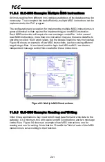
6)  Assign a tag to the XIO element. 

a)  Double-click on the XIO element located to the left of the MSG block.  

Type in N20:0/15 (MSG instruction’s enable bit).  This configuration 
causes the MSG instruction to automatically retrigger itself when it 
completes.  While this is acceptable for the purposes of this example, it 
can produce high network utilization.  In actual practice, it may be 
desirable to incorporate additional logic elements to allow triggering the 
MSG instruction at a specific rate or under specific conditions. 


7)  The program is now complete.  Refer to Figure 91. 


Figure 91: Completed PLC Program 


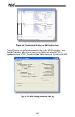
8)  Save, download, and run the program. 

a)  To view the 16-bit data values being read from the gateway, double-click 

the data file N18 under “Data Files” in the controller organizer view.  25 
16-bit word values starting at database address #2050 are being 
continuously read from the gateway and placed in the 25 sequential 
offsets of N18 starting at N18:1.  Refer to Figure 92.  We can see that 
N18:9 (database address 2068) has a value of 2525, N18:12 (database 
address 2074) has a value of 610, etc. 


Figure 92: Monitoring the Data Being Read from the Gateway 


Содержание ETH-1000

Страница 1: ...January 15 2012 ICC 10724 2012 Industrial Control Communications Inc ICC INDUSTRIAL CONTROL COMMUNICATIONS INC ETH 1000 Multiprotocol Ethernet RS 485 Gateway Instruction Manual...

Страница 2: ...ent in a system of any size In order to prevent danger to life or property it is the responsibility of the system designer to incorporate redundant protective mechanisms appropriate to the risk involv...

Страница 3: ...BACnet Firmware Version 2 300 Metasys Toshiba Firmware Version 2 200 Sullair Chillgard Firmware Version 2 400 FLN Basys Firmware Version 2 400 DMX 512 M Bus Firmware Version 2 300 AIN PDNP Firmware Ve...

Страница 4: ...ations that may be subjected to large shocks or vibrations Avoid installation locations that may be subjected to rapid changes in temperature or humidity Operating Environment Proper ground connection...

Страница 5: ...9 5 2 Power over Ethernet PoE 19 5 3 RS 485 Port Electrical Interface 20 6 Installation 22 6 1 Mounting the Gateway 22 6 1 1 Panel Wall Mounting 22 6 1 2 DIN Rail Mounting 23 6 2 Wiring Connections 24...

Страница 6: ...485 Protocol Configuration 72 8 8 1 A O Smith AIN Slave 72 8 8 2 A O Smith PDNP Master 77 8 8 3 BACnet MS TP Client 81 8 8 4 BACnet MS TP Server 88 8 8 5 TCS Basys Master 96 8 8 6 DMX 512 Master 102...

Страница 7: ...guration 166 10 8 3 Service Object Configuration 166 10 8 4 Submitting Changes 167 10 9 BACnet IP Client Menu 168 10 9 1 BACnet IP Client Enable 168 10 9 2 Device Object Configuration 168 10 9 3 Servi...

Страница 8: ...16 2 Network Configuration 182 10 16 3 MAC Address 183 10 16 4 Submitting Changes 183 10 17 Alarm Menu 184 10 17 1 Email Configuration 185 10 17 2 Alarm Configuration 186 10 17 3 Submitting Changes 18...

Страница 9: ...1 Overview 235 11 8 2 Tag Reference 235 11 8 3 SLC 5 05 Example Read Database 236 11 8 4 SLC 5 05 Example Multiple MSG Instructions 241 11 8 5 SLC 5 05 Example Reading and Writing 241 11 9 M Bus Mast...

Страница 10: ...266 12 Troubleshooting 267 13 Appendix A Database Endianness 269 13 1 Ex Modbus Profibus 271 13 2 Ex Modbus DeviceNet 272 13 3 Ex BACnet DeviceNet 273 13 4 Ex BACnet Modbus Analog Objects Registers 27...

Страница 11: ...visit http www iccdesigns com Before continuing please take a moment to ensure that you have received all materials shipped with your kit These items are ETH 1000 Gateway in plastic housing Documenta...

Страница 12: ...ateway also currently provides support for the following RS 485 based fieldbus protocols A O Smith AIN Slave A O Smith PDNP Master BACnet MS TP Client BACnet MS TP Server TCS Basys Master MSA Chillgar...

Страница 13: ...ve both value and time constraints and can be configured to retrigger at a fixed interval as long as the alarm condition continues to be satisfied Twenty individually configurable alarms are available...

Страница 14: ...ch This means that the gateway will perform any outstanding write services before resuming its round robin read request cycle Additionally the database and service objects provide the added benefit of...

Страница 15: ...e of an Analog Output on a remote BACnet device can vary from 500 to 500 a 16 bit signed data type should be used If the value can only vary from 0 to 150 for example an 8 bit unsigned data type may b...

Страница 16: ...trical Installations all regulations of the Occupational Safety and Health Administration and any other applicable national regional or industry codes and standards DO NOT install operate perform main...

Страница 17: ...re Preventive maintenance and inspection is required to maintain the gateway in its optimal condition and to ensure a long operational lifetime Depending on usage and operating conditions perform a pe...

Страница 18: ...c or your local distributor 4 7 Disposal Contact the local or state environmental agency in your area for details on the proper disposal of electrical components and packaging Do not dispose of the un...

Страница 19: ...nt RS 485 TX and RX LEDs Shielded RJ45 Ethernet jack USB connector Ethernet activity LED green Ethernet link LED amber Module Status MS and Network Status NS LEDs MAC ID on bottom Chassis GND RS 485 t...

Страница 20: ...teway s terminal block at terminals TB 5 POWER and TB 6 GND as highlighted in Figure 1 Figure 1 Terminal Block Power Supply Connections 5 2 Power over Ethernet PoE The gateway supports the IEEE 802 3a...

Страница 21: ...ted power supply to the power supply terminal block 5 3 RS 485 Port Electrical Interface In order to ensure appropriate network conditions signal voltage levels etc when using the gateway s RS 485 por...

Страница 22: ...21 ICC Figure 3 highlights the terminals on the gateway s terminal block that are specific to RS 485 connections Figure 3 Terminal Block RS 485 Connections...

Страница 23: ...om of the enclosure A DIN rail adapter with two pre mounted screws is provided for mounting the gateway on a DIN rail The user must choose the appropriate hardware for mounting the gateway on a panel...

Страница 24: ...clip the DIN rail adapter onto the DIN rail and mount the gateway on the screws the screws should already be seated into the adapter at the proper height Refer to Figure 7 Figure 8 and Figure 9 Figure...

Страница 25: ...y 6 3 Grounding Grounding is of particular importance for reliable stable operation Communication system characteristics may vary from system to system depending on the system environment and groundin...

Страница 26: ...2 for further details Table 1 Module Status LED LED State Indication Off No power Green Gateway has power and is functioning normally Flashing Green The gateway has established a USB connection Flashi...

Страница 27: ...protocol only that data exists and is being detected Also note that if a 2 wire RS 485 network is in use that the gateway s RX LED will light in conjunction with the TX LED as transmitting devices on...

Страница 28: ...e utility will automatically select the correct device and upload the current configuration from the connected device General Configuration To configure the gateway enable the desired Ethernet protoco...

Страница 29: ...the toolbar Note that if a newer version exists for the firmware installed on the device a message will be displayed in the Status box indicating an update is available Resetting the Device To reset...

Страница 30: ...y Once the desired settings are configured click Save IP Settings in the Tasks group to save the settings on the gateway Product Information Group This section displays the Product Name Application Fi...

Страница 31: ...ther information Note that this feature is only used with slave server protocols This is not the same as the timeout value used for master client protocols For more information refer to section 8 4 Th...

Страница 32: ...esired data type from this dropdown Value This is the fail safe timeout value that every data element in this timeout object will be automatically written to upon processing of a timeout event trigger...

Страница 33: ...mber of milliseconds the device will wait before responding to a request This is a useful feature for certain master devices or infrastructure components such as radio modems that may require a given...

Страница 34: ...d to store each object in the service object The data type also specifies whether the value should be treated as signed or unsigned when converting it to a real number to send over the network Note th...

Страница 35: ...en a configuration that contains a service object status is downloaded to the device or uploaded from the device that address is automatically added into the Status list in the Monitor tab status addr...

Страница 36: ...lick the Create button This may be a useful feature for situations in which many objects must be configured but only a few fields such as the database address and type are different Deleting an Object...

Страница 37: ...a note of the new settings whenever these authentication credentials are changed as they must be entered whenever the web page is accessed an FTP session is initiated or when a configuration change i...

Страница 38: ...nicating with require additional time between requests or to reduce overall network utilization If no additional time is required set this field to 0 8 7 2 1 Device Object Configuration Group The Devi...

Страница 39: ...ntry of a starting database address that will cause the service object to run past the end of the database The highest valid database address therefore will depend on the targeted data type as well as...

Страница 40: ...ly to input objects Check Write to enable writing when values encompassed by this service object change in the gateway s database these changes will be written down to the targeted remote device Prior...

Страница 41: ...unique across the entire BACnet network Enter a string of between 1 and 16 characters in length Instance Number This field is the BACnet Device Object s instance number The instance number must be uni...

Страница 42: ...neously assigned to one database address each binary object mapping to a single bit of that byte in the database It is possible to map binary objects to multiple bits within the designated database lo...

Страница 43: ...state is active low select Reverse from this dropdown menu For further detail refer to the Bitmask behavioral description above Data Type Applies to analog objects only This field specifies how many...

Страница 44: ...43 ICC 8 7 4 BBMD Currently the BBMD is only configurable via the embedded web page Refer to section 10 11...

Страница 45: ...vice objects targeting the remote endpoint defined by the connection object the service objects are serviced sequentially Several different types of class 3 requests are available to match the capabil...

Страница 46: ...resides A Slot value of NA not applicable will ignore the Slot Message Type Select the desired message type for the service object from this dropdown menu Class 1 is the implicit I O messaging type Pr...

Страница 47: ...rward open request While this assembly instance number is required no additional configuration data is included in the forward open request Some EtherNet IP servers ignore this field Enter a value of...

Страница 48: ...e first byte of this service object s data value will be mapped Enter a value between 0 and 4095 0x0 0xFFF Num Bytes This field specifies the number of bytes starting from the designated Database Addr...

Страница 49: ...values up to 65 535 and 32 bit can have values up to 4 294 967 295 Multiplier This field is the amount that associated network values are scaled by prior to being stored into the database or after be...

Страница 50: ...e Triggering Mechanism to determine the specific behavior of write services DB Addr Database Address This field specifies the address in the gateway s database where the first 16 bit element of this s...

Страница 51: ...ype with the DB Data Type Note that each data type has its own range limitations 8 bit can have values up to 255 16 bit can have values up to 65 535 and 32 bit can have values up to 4 294 967 295 Num...

Страница 52: ...l or by new data values being actively read into the database via service objects associated with a client protocol To manually activate a service object uncheck the Auto Trigger checkbox and enter a...

Страница 53: ...e object data has changed Once the request has been completed either successfully or unsuccessfully the gateway will update the database with the current data if the service object is read only update...

Страница 54: ...he EtherNet IP specification and is intended to signify when the client is in a running state or an idle state A running state run idle flag Run is indicated whenever the client is performing its norm...

Страница 55: ...ase from which the gateway s produced data will be taken Enter an address between 0 and 4095 0x0 0xFFF Consumed Data Start Address This is the starting address in the database at which the gateway s c...

Страница 56: ...55 ICC 8 7 7 CSP Client CSP utilizes the Typed Read and Typed Write services and is configured using the EtherNet IP client service object Refer to section 8 7 5...

Страница 57: ...56 ICC 8 7 8 CSP Server To enable the CSP server simply enable the EtherNet IP server No additional configuration is required Refer to section 8 7 6...

Страница 58: ...objects must always be configured to utilize a specific connection object at least one connection object must initially be created before any service objects can be created For more information on ser...

Страница 59: ...58 ICC connection object which improves performance by allowing these service objects to be processed in parallel...

Страница 60: ...59 ICC Figure 10 MELSEC Client Concept...

Страница 61: ...This drop down box designates the protocol for the connection If SLMP is selected the Frame Type is fixed to 3E frame Frame Type This drop down box designates the frame type to use when communicating...

Страница 62: ...r of the target station The Module I O Number is only configurable for SLMP connections Enter a value between 0x3D0 and 0x3D3 0x3E0 and 0x3E3 or 0x3FF Device Code Select the desired device code MELSEC...

Страница 63: ...alue should be limited to 256 words If a larger value is entered the driver will internally limit the value to 256 The targeted server may also impose additional limitations please refer to the MELSEC...

Страница 64: ...heck MELSEC Server in the Protocol dropdown menu to enable the driver and then click on the MELSEC Server subtab 8 7 10 1 Protocol Selection Group TCP Port The server TCP port must be specified before...

Страница 65: ...ect at least one connection object must initially be created before any service objects can be created For more information on service objects refer to section 8 5 Each register input or holding in a...

Страница 66: ...f registers associated with this service object Enter a value between 1 and 65535 For coil status and input status types this field defines the starting discrete number for a range of discretes associ...

Страница 67: ...ly Check Write to enable writing when values encompassed by this service object change in the gateway s database these changes will be written down to the targeted server When writes are enabled the d...

Страница 68: ...with registers 100 and 101 stored as the first 32 bit Unsigned value and registers 102 and 103 stored as the next 32 bit Unsigned value in the gateway s database Word Count Enable Word Count to encod...

Страница 69: ...timer therefore it is suggested that users read the ICC whitepaper titled A Discussion of Modbus TCP Server Side Timeout Processing which can be found in the documents section at http www iccdesigns c...

Страница 70: ...rd order i e the most significant 16 bit word is before the least significant 16 bit word Word Size Register Enable Word Size Register if each target register is 16 bits wide but two 16 bit registers...

Страница 71: ...ster pair as well as whether the internal value should be treated as signed or unsigned when converted to a floating point number for transmission over the network Select the desired data type from th...

Страница 72: ...ntify PROFINET devices Enter a string between 1 and 32 characters in length Produced Data Start Address This is the starting address in the database from which the gateway s produced data will be take...

Страница 73: ...ion on parameter mapping refer to section 11 1 2 8 8 1 1 Protocol Selection Group Protocol Select AO Smith AIN Slave from this dropdown menu Baud Rate Select the desired network baud rate from this dr...

Страница 74: ...tabase Read Enable Check Read to enable reading capturing the values of parameters from a broadcast All read enabled service objects will be used to compare block and parameter numbers for each master...

Страница 75: ...ture points increasing the Instance by 1 and Database Addr by 2 each time o Create objects for the setpoints Enter the following Select Analog Output from the Type selection group Enter Setpoint Temp...

Страница 76: ...ol the setpoint values Enter 0 into the Block Num field Enter 6 into the Start Param field Enter 2 into the Num Params field Enter 100 into the Database Addr field Check both the read and write functi...

Страница 77: ...76 ICC Note that the database endianness is arbitrary in this example as both protocols will access the database uniformly regardless of whether big or little endian storage is selected...

Страница 78: ...quests This may be useful if devices require additional time between requests If no additional delay time is needed set this field to 0 For more information refer to section 8 4 8 8 2 2 PDNP Service O...

Страница 79: ...d in 16 bits in the database Read Enable Check Read to enable reading the service object will continuously read from the device unless a pending Write exists Write Enable Check Write to enable writing...

Страница 80: ...menu Enter 0 01 into the Multiplier field Select Celsius 62 from the Units dropdown menu Click Create Repeat these steps for the other two temperature points increasing the Instance by 1 and Database...

Страница 81: ...12 for the Multiplier Click Create Finishing Up Download the configuration to the gateway see section 8 1 for more information on downloading a configuration to a device Connect the gateway to the boi...

Страница 82: ...Baud Rate Select the network baud rate from this dropdown menu Address This field is the node address that the gateway will reside at on the network Enter a value between 0 and 127 Scan Rate This is t...

Страница 83: ...r to section 8 6 Type The radio buttons in this group select the BACnet object type Choose from Analog Input Analog Output Analog Value Binary Input Binary Output or Binary Value Description This fiel...

Страница 84: ...ype Applies to analog objects only This field specifies how many bytes are used to store present value data for each BACnet object in this service object as well as whether the value should be treated...

Страница 85: ...the gateway for end to end communication using BACnet IP Server and BACnet MS TP Client Let s assume that we have an installation that has recently been upgraded to use Ethernet communications and wi...

Страница 86: ...0 Click Create For the second binary input enter the following Select Binary Input from the Type selection group Enter 1102 into the Instance field Enter 100 into the Database Addr field Enter 0x02 in...

Страница 87: ...BACnet IP objects that were created in the previous step o We can create a single service object for both analog inputs Select Analog Input from the Type selection group Enter the device instance of t...

Страница 88: ...instance of the drive in the Dest Dev Inst field Enter 1670 into the Start Inst field Enter 2 into the Num Insts field Enter 300 into the Database Addr field Click Create Finishing Up Download the co...

Страница 89: ...Group The Device Object Configuration group contains several fields that must be appropriately set for each device residing on a BACnet network Device Name This field is the BACnet Device Object s na...

Страница 90: ...he database address where the BACnet object s present value will reside Enter a value between 0 and 4095 0x0 0xFFF A note for analog objects Depending on the designated Data Type the maximum allowable...

Страница 91: ...bject is read by a BACnet client the Bitmask is used to determine the active inactive state of the object by inspecting the value in the designated database address at the bit location s indicated in...

Страница 92: ...n from different floors of a building There are 3 floors floor 1 has 3 analog values at instances 1000 1001 and 1002 for monitoring the floor status and 3 analog values at instances 1003 1004 and 1005...

Страница 93: ...s command data For the first object enter the following Select Analog Value from the Type selection group Enter F1 Cmd Data 1 into the Object Name field Enter 1003 into the Instance field Enter 100 in...

Страница 94: ...r field Select 32 bit Unsigned from the Data Type dropdown menu Enter 1 into the Multiplier field Select No Units 95 from the Units dropdown menu Click Create Repeat these steps for the other two obje...

Страница 95: ...ed Data Byte 19 High byte Produced Data Byte 20 Upper byte Floor 2 Monitor Data 3 AV2002 Produced Data Byte 21 Low byte Produced Data Byte 22 Middle byte Produced Data Byte 23 High byte Produced Data...

Страница 96: ...yte Floor 2 Command Data 3 AV2005 Consumed Data Byte 21 Low byte Consumed Data Byte 22 Middle byte Consumed Data Byte 23 High byte Consumed Data Byte 24 Upper byte Floor 3 Command Data 1 AV3003 Consum...

Страница 97: ...e after sending a request Scan Rate This is the time the device will wait between sending requests This may be useful if drives require additional time between requests If no additional delay time is...

Страница 98: ...is 0 01 then the network data can achieve a maximum value of only 655 since 65535 is the maximum value that can be stored in 16 bits in the database Offset This field is the amount added to associated...

Страница 99: ...nd heating and cooling setpoints We also wish to enable and disable the outdoor heat The temperatures can be monitored by mapping BACnet Analog Inputs and the outdoor heat enable can be controlled by...

Страница 100: ...rature and Outdoor temperature are scaled differently we must create 2 separate service objects The setpoints are scaled the same so one service object can be created for both values o Create one serv...

Страница 101: ...e setpoint temperatures ranges from 40 to 90 and the raw data values received from the thermostat are 0 to 255 enter 5 1 for the Multiplier and 40 for the Offset Click Create o Create a final service...

Страница 102: ...BACnet Object 0 1 Room Temperature Analog Input 0 2 3 Outdoor Air Temperature Analog Input 1 4 5 Heating Setpoint Analog Input 2 6 7 Cooling Setpoint Analog Input 3 64 Outdoor Heating Enable Binary O...

Страница 103: ...r a number between 1 and 512 8 8 6 3 Configuration Example This example will configure the gateway for end to end communication using DMX 512 Master and Ethernet IP Server Say for instance a museum ha...

Страница 104: ...ay to the two lights and the BAS Configure one of the light s DMX addresses to 1 and the other to 5 Where are the control values Database Address Light Parameter Ethernet IP Byte 0 Red for Light 1 Pro...

Страница 105: ...onfiguration Example This example will configure the gateway for end to end communication using DMX 512 Slave and Modbus TCP Client Say for instance a stage setup has a variety of DMX enabled lights a...

Страница 106: ...o We can create one service object to command both the X and Y positions Select Holding Register from the Type selection Select the previously created connection from the Connection dropdown Enter th...

Страница 107: ...dbus Register 0 X Coarse Adjustment 49 Register 100 Upper Byte 1 X Fine Adjustment 50 Register 100 Lower Byte 2 Y Coarse Adjustment 51 Register 101 Upper Byte 3 Y Fine Adjustment 52 Register 101 Lower...

Страница 108: ...devices require additional time between requests If no additional delay time is needed set this field to 0 For more information refer to section 8 4 8 8 8 2 M Bus Service Object Configuration This sec...

Страница 109: ...ng stored into the database Note that the multiplier imposes range limitations on network data values For example if the multiplier is 0 01 then the network data can achieve a maximum value of only 65...

Страница 110: ...er to select the desired function for the service object that will be encoded into the function field of the DIB LVAR This field is enabled when the Variable Length data type is selected in the Data F...

Страница 111: ...ee section 8 1 for more information on selecting a device Click on the Ethernet Configuration subtab Click Use a static IP address and enter an IP address for the gateway to reside at on the SCADA sys...

Страница 112: ...Bus converter Create Service Objects to read the desired data o Create one service object to monitor the volume flow Enter the address of the heat meter into the Dest Address field Enter 0 into the D...

Страница 113: ...check Manually Enter Bytes in the Data Information Block DIB group and select No Data Auto Detect from the Data Field dropdown Uncheck Manually Enter Bytes in the Value Information Block VIB group and...

Страница 114: ...information refer to section 8 4 8 8 9 2 N2 Service Object Configuration The following describes the configurable fields for a Metasys N2 service object For more information on N2 service object edit...

Страница 115: ...ier Applies to analog and internal objects only This field is the amount that associated network values are scaled by prior to being stored into the database or after being retrieved from the database...

Страница 116: ...nfigure the Ethernet port using the above requirements Connect the gateway to the PC via a USB mini type B cable Open the configuration utility and select the ETH 1000 see section 8 1 for more informa...

Страница 117: ...into the Database Addr field Click Create o To command the frequency command we must create a service object for that analog output Select Analog Output from the Type selection group Enter the addres...

Страница 118: ...Binary Input 2 Discrete 98 Register 7 bit 1 Reverse Stop Binary Input 3 Discrete 99 Register 7 bit 2 13 15 Unused 16 17 Frequency Command Analog Output 2 Register 9 Lower 16 bits 18 19 Register 10 Upp...

Страница 119: ...evice waits before responding to master requests This may be useful if the Metasys master communicating to the gateway requires additional time before it can process a response to its request If no de...

Страница 120: ...dress each binary object mapping to a single bit of that byte in the database It is possible to map binary objects to multiple bits within the designated database location Such a configuration allows...

Страница 121: ...le Open the configuration utility and select the ETH 1000 see section 8 1 for more information on selecting a device Click on the Ethernet Configuration subtab Click Use a static IP address and enter...

Страница 122: ...enter the following Select Analog Output from the Type selection group Enter F2 Mon Data 1 into the Object Name field Enter 4 into the Instance field Enter 12 into the Database Addr field Select 32 b...

Страница 123: ...Addr by 4 each time o Create input objects for floor 3 s command data For the first object enter the following Select Analog Input from the Type selection group Enter F3 Cmd Data 1 into the Object Nam...

Страница 124: ...duced Data Byte 19 High byte Produced Data Byte 20 Upper byte Floor 2 Monitor Data 3 AO6 Produced Data Byte 21 Low byte Produced Data Byte 22 Middle byte Produced Data Byte 23 High byte Produced Data...

Страница 125: ...byte Floor 2 Command Data 3 AI6 Consumed Data Byte 21 Low byte Consumed Data Byte 22 Middle byte Consumed Data Byte 23 High byte Consumed Data Byte 24 Upper byte Floor 3 Command Data 1 AI7 Consumed D...

Страница 126: ...s dropdown menu Parity Select the desired network parity and number of stop bits from this dropdown menu Timeout This is the time in milliseconds that the device will wait for a response from a remote...

Страница 127: ...00 Database Addr This field defines the database address where the first register discrete of this service object will be mapped Enter a value between 0 and 4095 Note that the configuration utility wi...

Страница 128: ...r coil status types note that this feature is always enabled with function code 15 Force Multiple Coils Service Object Status If it is desired to reflect the status of this service object check the Re...

Страница 129: ...pair in this service object as well as whether the value should be treated as signed or unsigned when converted to a floating point number for transmission over the network Select the desired data ty...

Страница 130: ...S 485 port using the above requirements Click on the RS 485 Configuration tab Select Modbus RTU Master from the protocol dropdown menu Enter the Baud Rate and Parity settings to match that of the driv...

Страница 131: ...responding to master requests This may be useful if the Modbus master communicating to the gateway requires additional time before it can process a response to its request If no delay is required set...

Страница 132: ...lues are scaled by prior to being stored into the database or after being retrieved from the database Upon retrieval from the database raw data is multiplied by the multiplier to produce a network val...

Страница 133: ...as the number of 16 bit words to be transferred If not enabled the quantity of registers field will be interpreted as the number of 32 bit registers to be transferred Data Type This field specifies h...

Страница 134: ...RS 485 Configuration tab Select Modbus RTU Slave from the protocol dropdown menu Enter the Baud Rate and Parity settings to match that of the PLC Enter the Address for the gateway to reside at on the...

Страница 135: ...eld Click Create o Remap floor 1 s command data registers Enter 3003 into the Start Reg field Enter 3 into the Num Regs field Enter 112 into the Database Addr field Click Create Finishing Up Download...

Страница 136: ...te Floor 3 Monitor Data 3 Register 3002 Produced Data Byte 17 Lower byte Produced Data Byte 18 Upper byte Floor 1 Command Data 1 Register 1003 Consumed Data Byte 1 Lower byte Consumed Data Byte 2 Uppe...

Страница 137: ...vice Object Configuration This section describes the configurable fields for a Modbus sniffer service object For more information on Modbus service object editing options refer to section 8 6 Type Thi...

Страница 138: ...ltiplier before being stored into the database Note that the multiplier imposes range limitations on network data values For example if the multiplier is 0 01 then the network data can achieve a maxim...

Страница 139: ...odbus network in a non intrusive manner which simplifies installation and nearly eliminates integration effort when applied to an already functioning Modbus network In this case we wish to monitor the...

Страница 140: ...Regs field Enter 6 into the Database Addr field Click Create Finishing Up Download the configuration to the gateway see section 8 1 for more information on downloading a configuration to a device Con...

Страница 141: ...m the protocol dropdown menu The Siemens FLN slave driver supports fully configurable FLN objects for the creation of new FLN applications Because the FLN application must first be approved before use...

Страница 142: ...rence for the user Enter a string of up to 16 characters in length Dest Address This field indicates the destination address of the controller on the network that will be accessed by this service obje...

Страница 143: ...Write Enable and Function Code Selection Check Write to enable writing when values encompassed by this service object change in the gateway s database these changes will be written down to the targete...

Страница 144: ...base Addr field Uncheck the write function code check box these are monitor only parameters so there will be no need to write to them Click Create o Create a second service object to monitor the run s...

Страница 145: ...ntroller Parameter Parameter Index Database Address P1 107 0 1 P2 108 2 3 P3 109 4 5 P4 110 6 7 T1 111 8 9 T2 112 10 11 T3 113 12 13 T4 114 14 15 T5 115 16 17 run status 103 18 19 unload pressure 5 32...

Страница 146: ...onse from a drive after sending a request Scan Rate This is the time the device will wait between sending requests This may be useful if drives require additional time between requests If no additiona...

Страница 147: ...th acceleration time 1 and deceleration time 1 via a single service object then enter 9 in the Start Param field and 2 in the Num Params field This will cause the service object to access both paramet...

Страница 148: ...writing to them Service Object Status If it is desired to reflect the status of this service object check the Reflect Status checkbox and enter a database address between 0 and 4080 0x0 0xFF0 at whic...

Страница 149: ...cts for reading the drive status parameters one which accesses parameters FE00 and FE01 and one which accesses parameters FE03 and FE04 o Create one service object to monitor the output frequency and...

Страница 150: ...t frequency FE00 Produced Data Byte 1 Lower byte Produced Data Byte 2 Upper byte Drive status word FE01 Produced Data Byte 3 Lower byte Produced Data Byte 4 Upper byte Output current FE03 Produced Dat...

Страница 151: ...the embedded web server and therefore these specific configuration files are only available via FTP Each time the gateway boots up it will interrogate the filesystem for the configuration files requir...

Страница 152: ...wser or a 3rd party FTP program whatever the computer operating system is configured for by default This example will assume that a web browser Microsoft Internet Explorer is configured as the default...

Страница 153: ...ote that the indicated procedure prompts and capabilities outlined here can vary depending on such factors as the installed operating system firewalls and service packs In the Address field type in ft...

Страница 154: ...ve password default is icc and click Log On Figure 15 FTP Authentication Windows Explorer will then display the filesystem s contents refer to Figure 16 You can now perform normal file manipulation ac...

Страница 155: ...dress of the target gateway The FTP client will connect to the unit and then prompt for the username and case sensitive password defaults are root and icc respectively Upon successful entry of the aut...

Страница 156: ...155 ICC Figure 18 Listing Files with ls Command Figure 19 Copying a File from the Unit With get Command Figure 20 Copying a File to the Unit With put Command...

Страница 157: ...Connect button when done Core FTP LE will then try to connect and authenticate to the FTP server and if successful will populate the right hand side of the main page with the unit s filesystem content...

Страница 158: ...157 ICC Figure 22 Core FTP in Connected State...

Страница 159: ...across the globe In order to view the gateway s web page the free Adobe formerly Macromedia Flash Player browser plug in is required If the plug in is not already installed on your computer then your...

Страница 160: ...dow and no parameter values are shown this is typically indicative of port 2000 being blocked by a firewall or Ethernet router situated between the client computer and the gateway 10 2 Authentication...

Страница 161: ...on Menu Tree 10 4 Activity Window Figure 26 shows the Activity Window which is located at the top of the web page This window displays various informational messages regarding the status of the gatewa...

Страница 162: ...n The radix selection buttons provide the ability to change the data display and entry radix between decimal and hexadecimal formats When DEC is selected the current values will be displayed in decima...

Страница 163: ...ility Refer to Figure 27 Figure 27 MELSEC Client Menu 10 6 1 MELSEC Client Enable Check to enable the MELSEC client driver 10 6 2 Connection Object Configuration For more information regarding MELSEC...

Страница 164: ...settings to the gateway s filesystem Note that because these configuration elements are read from the filesystem only when the gateway boots up the act of submitting configuration changes will also r...

Страница 165: ...to Figure 28 Figure 28 EtherNet IP Client Menu 10 7 1 EtherNet IP Client Enable Check to enable the EtherNet IP client driver 10 7 2 Connection Object Configuration For more information regarding Eth...

Страница 166: ...ese settings to the gateway s filesystem Note that because these configuration elements are read from the filesystem only when the gateway boots up the act of submitting configuration changes will als...

Страница 167: ...to Figure 29 Figure 29 Modbus TCP Client Menu 10 8 1 Modbus TCP Client Enable Check to enable the Modbus TCP client driver 10 8 2 Connection Object Configuration For more information regarding Modbus...

Страница 168: ...se settings to the gateway s filesystem Note that because these configuration elements are read from the filesystem only when the gateway boots up the act of submitting configuration changes will also...

Страница 169: ...figuration utility Refer to Figure 30 Figure 30 BACnet IP Client Menu 10 9 1 BACnet IP Client Enable Check to enable the BACnet IP client driver 10 9 2 Device Object Configuration For information rega...

Страница 170: ...se settings to the gateway s filesystem Note that because these configuration elements are read from the filesystem only when the gateway boots up the act of submitting configuration changes will also...

Страница 171: ...P Server Enable Check to enable the BACnet IP server driver 10 10 2 Device Object Configuration For information regarding these fields refer to section 8 7 3 1 10 10 3 BACnet Object Configuration For...

Страница 172: ...filesystem Note that because these configuration elements are read from the filesystem only when the gateway boots up the act of submitting configuration changes will also reset the gateway Please all...

Страница 173: ...2 Figure 32 BBMD Server Menu 10 11 1 BBMD Enable Check to enable the BBMD driver 10 11 2 Broadcast Distribution Table BDT Configuration In order for the BBMD to be effective all BBMD entries must be i...

Страница 174: ...ate the FDT IP Address IP address of the foreign device Port UDP port to receive BACnet IP packets Time to Live The time in seconds within which a foreign device must re register Remaining The actual...

Страница 175: ...r subtab in the configuration utility Refer to Figure 33 Figure 33 EtherNet IP Server Menu 10 12 1 EtherNet IP Enable Check to enable the EtherNet IP server driver 10 12 2 Run Idle Flag Behavior For m...

Страница 176: ...n elements have been changed the submit button must be clicked in order to write these settings to the gateway s filesystem Note that because these configuration elements are read from the filesystem...

Страница 177: ...essible via the MELSEC Server subtab in the configuration utility Refer to Figure 34 Figure 34 MELSEC Server Menu 10 13 1 MELSEC Server Enable Check to enable the MELSEC server driver 10 13 2 TCP Port...

Страница 178: ...e settings to the gateway s filesystem Note that because these configuration elements are read from the filesystem only when the gateway boots up the act of submitting configuration changes will also...

Страница 179: ...he Modbus TCP subtab in the configuration utility Refer to Figure 35 Figure 35 Modbus TCP Server Menu 10 14 1 Modbus TCP Server Enable Check to enable the Modbus TCP server driver 10 14 2 Timeout Time...

Страница 180: ...ese settings to the gateway s filesystem Note that because these configuration elements are read from the filesystem only when the gateway boots up the act of submitting configuration changes will als...

Страница 181: ...ion utility Refer to Figure 36 Figure 36 PROFINET IO Menu 10 15 1 PROFINET IO Enable Check to enable the PROFINET IO driver 10 15 2 Device Identification For more information refer to Device Name in s...

Страница 182: ...te these settings to the gateway s filesystem Note that because these configuration elements are read from the filesystem only when the gateway boots up the act of submitting configuration changes wil...

Страница 183: ...nfiguration subtab in the configuration utility Refer to Figure 37 Figure 37 Network Settings Menu 10 16 1 Authentication Refer to section 8 7 1 1 10 16 2 Network Configuration Figure 38 shows the con...

Страница 184: ...ed the submit button must be clicked in order to write these settings to the gateway s filesystem Note that because these configuration elements are read from the filesystem only when the gateway boot...

Страница 185: ...and send emails to up to four recipients when a certain condition is detected The alarm conditions have both value and time constraints and can be configured to retrigger at a fixed interval as long a...

Страница 186: ...he SMTP port default 25 that the SMTP server listens for incoming emails on From Email Enter the email address that will appear as the sender s email address in the email headers To Emails Up to four...

Страница 187: ...ation elements which will be explained further below Figure 44 Alarm Configuration Box Alarm Selection This drop down box allows the selection of one of the twenty available alarms When an alarm is se...

Страница 188: ...ables e g status words where each bit of the database value indicates a different item however the Mask can be chosen to single out one or more specific data bits of the value Note that the alarms wil...

Страница 189: ...missions for this alarm will stop until the next time the alarm is triggered of course Subject Enter a string of up to 128 characters in length which will appear in the subject line of the alarm email...

Страница 190: ...isplay any database value via one of six different gauge types User defined engineering units data type scaling and range limits are also configurable Refer to Figure 45 Figure 45 Dashboard Menu 10 18...

Страница 191: ...nd signed vs unsigned of the data read from the configured address Multiplier The multiplier value is a floating point number that is used to scale the raw value contained in the database As its name...

Страница 192: ...roviding a simple historical reference The Min Value attribute is not configurable this gauge always starts at 0 BarGraph Refer to Figure 48 This type of meter implements a linear bar graph display fo...

Страница 193: ...hermometer Refer to Figure 51 This type of meter implements the universally identifiable thermometer display format Hovering the mouse pointer over the red mercury portion of the graph pops up a toolt...

Страница 194: ...ebooting of the gateway the changes take effect immediately and the gateway continues its operation without interruption Figure 53 Zooming Gauge Usage Tip At times it may be convenient to zoom in on a...

Страница 195: ...out menu provides access to configuration items related to timeout processing Refer to Figure 54 Figure 54 Timeout Menu 10 19 1 Timeout Object Configuration For detailed information regarding timeout...

Страница 196: ...work including local and remote displays and other interface devices 11 1 2 AIN Service Objects The AIN slave driver uses service objects to describe what services the gateway should perform Each serv...

Страница 197: ...PDNP Service Objects The PDNP master driver uses service objects to describe what services the gateway should perform For each service object the gateway will continually read the parameters defined...

Страница 198: ...nd 115200 The device can be configured as a BACnet IP client and or BACnet IP server BBMD and MS TP client and or MS TP server BACnet Standard Device Profile Annex L BACnet Operator Workstation B OWS...

Страница 199: ...______ Point To Point EIA 232 Clause 10 baud rate s ______ Point To Point modem Clause 10 baud rate s ______ LonTalk Clause 11 medium ______ Other ______ Device Address Binding Is static device bindi...

Страница 200: ...datatypes that are accepted in the case of a write property service and returned in the case of a read property service when targeting the present value property of each supported object type Object...

Страница 201: ...vision R App Software Revision R Protocol Version R Protocol Revision R Services Supported R Object Types Supported R Object List R Max APDU Length R Segmentation Support R APDU Timeout R Number APDU...

Страница 202: ...ad the present value of the defined BACnet object within the service object from the designated device storing the value s in the database if the read function is enabled When data in the database cha...

Страница 203: ...fined service objects and the destination address must be set to the network address of the device 11 3 2 4 BACnet Object Mapping Analog Objects Analog objects are mapped in the database as either an...

Страница 204: ...bjects which contain many different properties for any BACnet client on the network to access The gateway supports seven different BACnet objects Device Analog Input Analog Output Analog Value Binary...

Страница 205: ...address Dynamic Object Binding This service is used to discover the gateway s objects on the network Upon receiving a Who Has request on the network the gateway will generate an I Have response if tha...

Страница 206: ...stribution Table messages with a Read Broadcast Distribution Table Ack message that contains the current contents of the BDT Forwarded NPDU The gateway processes incoming and outgoing Forwarded NPDU m...

Страница 207: ...ed a write request is generated to the designated device notifying it of the changed parameter value s if the write function is enabled For more information on configuring Basys service objects refer...

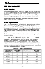
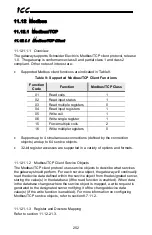
Страница 208: ...207 ICC SMin SMax Min Max multiplier Equation 1 SMin offset Equation 2...

Страница 209: ...shown on the display The gateway can be powered from the 12V supply on the Chillgard RT and Chemgard monitors by connecting J14 terminals 1 12V and 3 GND to terminals POWER and GND of the gateway resp...

Страница 210: ...describes the non configurable data mapping for the Chillgard Monitor protocol Each parameter is a 16 bit word containing either data values or bit wise data Note that for all bit wise parameters bit...

Страница 211: ...r S7 Gas Concentration S7 Alarm State Reserved 64 S8 Gas Number S8 Gas Concentration S8 Alarm State Reserved I O State This parameter is the I O state of the monitor module overall It may have the fol...

Страница 212: ...centration values and gas type to the gateway This occurs only when the monitor is showing the home screen on its display i e if the user navigates away from the monitor s home screen these bits will...

Страница 213: ...2b 68 Methane 119 Forane 18 R 143a 69 Butane 120 Halothane 19 R 152a 70 Propane 121 THF 20 R 227 71 N Pentane 122 Methyl Methacrylate 21 R 236fa 72 Styrene 123 HFE 7100 22 R 401A 73 Ethyl Benzene 124...

Страница 214: ...1234yf 101 O Xylene Sx Gas Concentration This parameter one for each of 8 samples is the current gas concentration sampled for that point Note that the gas concentration value will not be updated in t...

Страница 215: ...the DMX 512 master protocol refer to section 8 8 6 11 6 1 2 Connections While there are a variety of different DMX 512 connector types in existence most standard DMX 512 connectors use either XLR 5 p...

Страница 216: ...ls at any address within the 512 DMX channel range The DMX 512 slave protocol allows anything connected to the gateway to be controlled by a universal DMX controller device 11 6 2 1 Overview Some note...

Страница 217: ...aning of the data is pre defined at the time the connection is established which in turn minimizes the processing time of the node during run time I O messages are short and have low overhead which al...

Страница 218: ...are calculated by multiplying the RPI and Multiplier For class 1 client connections if the API actual packet interval returned by the server is within 10ms of the client s configured RPI setting then...

Страница 219: ...s 100 and 150 The following sections demonstrate specific examples of how to use EtherNet IP to transfer data between the gateway and Allen Bradley Logix brand PLCs 11 7 3 1 ControlLogix Examples Setu...

Страница 220: ...Download the configuration 9 Switch to online mode Right click on the 1756 ENBT A module in the I O Configuration and choose Properties 10 Select the Port Configuration tab from the Module Properties...

Страница 221: ...Interval RPI 1 Switch to offline mode 2 Right click on the 1756 ENBT A node under the I O Configuration in the controller organizer view and choose New Module 3 Choose Generic Ethernet Module in the S...

Страница 222: ...ccess data past the upper boundary of the database Equation 3 can be used to determine if the overall requested size is valid If the result of Equation 3 is less than or equal to 4095 4kbytes then the...

Страница 223: ...Properties Connection Tab Confirm the setting of the Requested Packet Interval RPI The RPI defines the amount of time in milliseconds between data exchanges across an I O connection The smallest RPI s...

Страница 224: ...cessing the database and as a bypass mechanism to access data on devices connected to the gateway by reference to tag names Tags are read via the EtherNet IP data table read service and tags are writt...

Страница 225: ...B_b_0 Access words starting at database address 2048 DB_w_2048 Access double words starting at database address 4092 DB_d_4092 11 7 3 3 2 ControlLogix Example Read Database Data This example program w...

Страница 226: ...NT 73 in the Data Type field This tag is an array of INTs that will be able to hold up to 73 16 bit values from the gateway Always make sure that the destination tag size is large enough to hold all e...

Страница 227: ...1 d Click OK 4 Configure the MSG instruction a Edit the Message Control field on the MSG instruction to use the previously created connection tag Refer to Figure 72 Figure 72 MSG Instruction Tag Assig...

Страница 228: ...ttings refer to Figure 74 i Enter the Path to the gateway A typical path is formatted as Local_ENB 2 target_IP_address where Local_ENB is the name of the 1756 ENBx module in the local chassis we named...

Страница 229: ...rposes of this example it can produce high network utilization In actual practice it may be desirable to incorporate additional logic elements to allow triggering the MSG instruction at a specific rat...

Страница 230: ...ead from the gateway s database and placed in the 21 sequential offsets of data_array starting at the 50th offset data_array 50 In Figure 78 we can see that data_array 50 has a value of 11860 data_arr...

Страница 231: ...uctions Figure 79 Reading Via Multiple MSG Instructions 11 7 3 3 4 ControlLogix Example Reading and Writing Often times applications may need to both read data from and write data to the gateway At a...

Страница 232: ...t also simultaneously being commanded in the background via I O messaging Indeterminate behavior can occur if MSG instructions and background I O data transfers are both writing to the same addresses...

Страница 233: ...e for 3E frames or a 4 character hexadecimal value for 1E frames Device codes are not limited to known device codes refer to Table 7 any device code supported by the targeted server may be specified I...

Страница 234: ...limitations on the number of points processed per communication 11 7 3 3 6 ControlLogix Example Read MELSEC Device Data This example program will demonstrate bypass access to device data on a MELSEC s...

Страница 235: ...Instruction Configuration This example of directly reading MELSEC device data via explicit messaging can easily be extended to accesses via multiple MSG instructions and to writing data by following t...

Страница 236: ...h Logical Binary Addressing and Logical ASCII Addressing are supported Only the Integer file type N is supported Note that data is accessed as 16 bit values The formula to calculate which database add...

Страница 237: ...l file enter a file number e g 20 set the type to Integer enter a descriptive name e g CONTROL and enter a number of elements e g 100 Click OK to create the file The control file is used to store conf...

Страница 238: ...Rung c Right click on the rung number of the new editable rung and select Append Instruction d Select the MSG instruction from the Input Output classification then click OK Refer to Figure 86 4 Add an...

Страница 239: ...ng a total of 25 16 bit word values from the database beginning at N30 50 address 2050 To configure this under This Controller set the Data Table Address field to N18 1 set the Size in Elements field...

Страница 240: ...239 ICC Figure 88 MSG Configuration General Tab Figure 89 MSG Configuration MultiHop Tab Figure 90 PLC Program after MSG Instruction Configuration...

Страница 241: ...tion at a specific rate or under specific conditions 7 The program is now complete Refer to Figure 91 Figure 91 Completed PLC Program 8 Save download and run the program a To view the 16 bit data valu...

Страница 242: ...ata file to store the received 16 bit word values but the storage locations must not overlap Figure 93 shows an example of two MSG instructions each accessing different target integer files It is evid...

Страница 243: ...ure 95 shows the configuration details of the write MSG instruction Note that this instruction will only be writing to one 16 bit word value N27 98 database address 1798 The source Data Table Address...

Страница 244: ...ce object addresses one data element which is defined by the Data Information Block DIB and Value Information Block VIB To read data when enabled the gateway sends a REQ_UD2 request to the target devi...

Страница 245: ...0 Batch Read Word 0x01 Batch Write Bit 0x02 and Batch Write Word 0x03 commands are supported All MELSEC communication is conducted over only TCP IP Some other notes of interest are Supports auto detec...

Страница 246: ...de Annunciator F Bit 93 H N A Counter Coil CC Bit C3 H 4343 H Counter Contact CS Bit C4 H 4353 H Counter Current Value CN Word C5 H 434E H Data Register D Word A8 H 4420 H Direct Input DX Bit A2 H N A...

Страница 247: ...described via Equation 6 point 2 address Equation 6 Other notes of interest are Supports up to 8 simultaneous connections The TCP port is user configurable refer to 8 7 10 1 The max MELSEC frame size...

Страница 248: ...socket life cycles gracefully and do not abandon outstanding requests If a socket timeout occurs regardless of whether it was due to a communication lapse or abnormal socket error the driver will trig...

Страница 249: ...according to the Metasys N2 specification Connect the N2 bus wiring to the RS 485 port by using twisted pair cable connected as shown in Figure 97 Connect the N2 wire to terminal A the N2 wire to ter...

Страница 250: ...ed N2 object within the service object from the designated device storing the value s in the database if the read function is enabled When data in the database changes where the N2 objects are mapped...

Страница 251: ...2 specification Connect the N2 bus wiring to the RS 485 port by using twisted pair cable connected as shown in Figure 98 Connect the N2 wire to terminal A the N2 wire to terminal B and the network gro...

Страница 252: ...bjects are used for monitoring discrete digital status items BI objects support COS alarm enabling and normal alarm status indications A BI object will accept an override command but will not change i...

Страница 253: ...defined by the connection objects and up to 64 service objects 32 bit register accesses are supported in a variety of options and formats 11 12 1 1 2 Modbus TCP Client Service Objects The Modbus TCP c...

Страница 254: ...r assignments in the database In this way the read multiple registers read input registers and write multiple registers functions can be used to perform transfers of larger blocks of registers using f...

Страница 255: ...ly the register to address relationship can be described via Equation 7 1 register 2 address Equation 7 Additionally a register remap object can be created to map a register to a different address in...

Страница 256: ...in which that discrete resides can be determined by Equation 9 16 1 discrete bit Equation 9 Where discrete 1 65535 bit 0 15 and is the modulus operator which means that any fractional result or remai...

Страница 257: ...ptions and formats The following point types are supported in Modbus Service Objects o Holding Register o Input Register o Coil Status o Input Status 11 12 2 1 2 Modbus Service Objects The Modbus RTU...

Страница 258: ...en discrete 1 through 8 will be mapped to bit 0 through 7 respectively at address 320 discrete 9 through 16 will be mapped to bit 0 through 7 respectively at address 321 and discrete 17 through 19 wil...

Страница 259: ...the same data For example reading Holding Register 4 returns the same data as reading Input Register 4 By default registers are mapped into the database using the following scheme Register 1 is mappe...

Страница 260: ...ny given discrete the targeted bit in the register in which that discrete resides can be determined by Equation 12 16 1 discrete bit Equation 12 Where discrete 1 65535 bit 0 15 and is the modulus oper...

Страница 261: ...ingle Register 16 Force Multiple Registers The filtering of specific actions targeting registers of interest is fully configurable through service objects Both Holding and Input Registers are supporte...

Страница 262: ...quired on the interface card the module will be selected automatically according to the controller s configuration Slots 1 to 8 can all be utilized The size of the I O data is the sum of the modules i...

Страница 263: ...eIdentNumber represents the number of input bytes 0123 and the second half represents the number of output bytes 0045 5 Locate the last reference of IN2_OUT2 and change the Value to IN 0123 OUT 0045 6...

Страница 264: ...ddressed For these data objects the additional parameter numbers indicated in Table 14 have been assigned Table 14 Additional Supervisor Parameter Assignments Parameter Number Item Note Source 100 Cap...

Страница 265: ...function is enabled When data in the database changes where the parameters are mapped a write request is generated to the designated controller notifying it of the changed parameter value s if the wr...

Страница 266: ...ay exhibit an issue that can cause their RS 485 ports to stop communicating after a certain amount of time Please contact Toshiba technical support to confirm your configuration prior to using 2 wire...

Страница 267: ...ction is enabled When data in the database changes where the parameters are mapped a write request is generated to the designated drive notifying it of the changed parameter value s if the write funct...

Страница 268: ...blinking slowly sporadically or not at all Check connections and orientation of wiring between the network and the gateway Confirm that the protocol baud rate parity and address settings on the RS 48...

Страница 269: ...ration utility Any other number of flashes indicates an internal device error Please contact ICC for further assistance The device will not connect to the PC with the USB cable The USB cable is plugge...

Страница 270: ...higher addresses The endianness determines whether the most significant or least significant bytes are stored first Let s look at some examples that demonstrate this This example shows how the hex val...

Страница 271: ...nes a big endian order for multi byte data while DeviceNet defines a little endian order for multi byte data These networks exchange I O data by means of a bag of bytes approach whereas the gateway ne...

Страница 272: ...ed for big endian byte order when using Profibus In the example holding register 1 has a value of 0x1234 and holding register 2 has a value of 0x5678 When the Profibus device receiving the input data...

Страница 273: ...e gateway s database configured as little endian Because the DeviceNet specification defines multi byte values within the byte array to be interpreted as little endian it is recommended that the datab...

Страница 274: ...exchanged between an object value style network BACnet and a bag of bytes style network DeviceNet The key difference is that in this example BACnet Analog Value 0 is a 32 bit value as opposed to two...

Страница 275: ...t device interprets the 4 bytes of input data sent by the gateway the resulting 4 byte value is 0x78563412 thus receiving an incorrect value for Analog Value 0 Note that in this example as well the De...

Страница 276: ...the database with big endian byte ordering Figure 112 shows the values from the BACnet network being stored into the database with little endian byte ordering Regardless of the byte ordering scheme u...

Страница 277: ...e wise basis into the database When the database is configured for a little endian byte order binary value 1 8 corresponds to coil 1 8 binary value 9 16 corresponds to coil 9 16 and so on This can be...

Страница 278: ...277 ICC Figure 114 BACnet Modbus Binary Objects Discretes Big Endian...

Страница 279: ...from the gateway RX Counter This is a 32 bit counter that increments when the gateway successfully receives a valid packet RX Error Counter This is a 32 bit counter that increments when the gateway re...

Страница 280: ...Address 0xF1 Data Error 0xF2 Write To Read Only 0xF3 Read From Write Only 0xF4 Target Busy 0xF5 Target Error 0xF6 Cannot Execute 0xF7 Mode Error 0xF8 Other Error 0xF9 Memory Error 0xFA Receive Error...

Страница 281: ...ICC INDUSTRIAL CONTROL COMMUNICATIONS INC 1600 Aspen Commons Suite 210 Middleton WI USA 53562 4720 Tel 608 831 1255 Fax 608 831 2045 http www iccdesigns com Printed in U S A...

Отзывы: