


187
ICC
this address designates the database starting location for the multi-byte element
to be evaluated. For multi-byte elements, whether this designated address
represents the element’s high byte or low byte depends upon the current
database endianness setting.
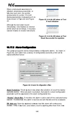
Logical Comparison:
Choose a comparison operator which will be used to
compare the current value of the indicated “Data Size” with the reference
“Comparison Value”. Available selections are “less than” (<), “less than or equal
to” (<=), “greater than” (>), “greater than or equal to” (>=), “not equal to” (!=), and
“equal to” (=).
Comparison Value:
The reference comparison value is comprised of three
subcomponents: a “Data Size” field, a “Mask” field, and a “Value” field. Each
time the alarm is evaluated, the current value at the indicated “DB Address” is
first bit-wise “AND”ed with the “Mask” field. The resulting derived value is then
compared with the “Value” field by way of the “Logical Comparison” operator.
While the “Mask” field is always a hexadecimal number, the display and entry
radix of the “Value” field can be changed between decimal and hexadecimal with
the associated “DEC” and “HEX” buttons.
Database values that correspond to “analog” process variables (e.g. frequencies,
voltages, counters etc.) should typically have their “Mask” fields set to all F’s
(0xFF for 8-bit, 0xFFFF for 16-bit, and 0xFFFFFFFF for 32-bit), which causes all
data bits to be retained for the “Value” field comparison. For values that
correspond to “enumerated” process variables (e.g. status words where each bit
of the database value indicates a different item), however, the “Mask” can be
chosen to single out one or more specific data bits of the value.
Note that the alarms will evaluate the designated database location regardless of
the meaning of the value contained there. What this means is that alarms can
react to not only process values that are being read and/or written via the various
connected networks, but also to ancillary items such as “reflect status” counters
or error indicators. As an example, the alarm shown in Figure 44 targets the 32-
bit “RX Error Counter” element of a status information structure that was
presumably placed at database address 110 (the “RX Error Counter” element is
located 8 bytes in from the start of the structure, thereby resulting in a required
address of 118: refer to Appendix B: Status Information). If the service object
associated with this status information structure accumulates more than 100
errors, then this alarm will trigger and notify the appropriate plant maintenance
personnel to perform an inspection.
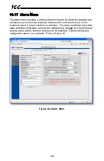
The Condition Must Remain True For A Minimum Of:
Alarm analysis
processing is performed by the gateway once per second. Enter the number of
seconds that the condition must be continuously evaluated as “true” for the alarm
to be triggered. A time of 0 seconds means that just a single evaluation of “true”
will immediately trigger the alarm.
Send Additional Reminders While The Condition Remains True:
If this
check box is unchecked, then only one email transmission event will occur when
an alarm condition is triggered: further email transmissions will not be attempted
Содержание ETH-1000
Страница 44: ...43 ICC 8 7 4 BBMD Currently the BBMD is only configurable via the embedded web page Refer to section 10 11...
Страница 60: ...59 ICC Figure 10 MELSEC Client Concept...
Страница 158: ...157 ICC Figure 22 Core FTP in Connected State...
Страница 208: ...207 ICC SMin SMax Min Max multiplier Equation 1 SMin offset Equation 2...
Страница 278: ...277 ICC Figure 114 BACnet Modbus Binary Objects Discretes Big Endian...


