Server controls, LEDs, and power
This section describes the controls and light-emitting diodes (LEDs) and how to turn
the server on and off.
Front view
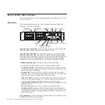
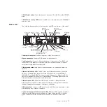
The following illustration shows the controls, light-emitting diodes (LEDs), and
connectors on the front of the server.
0
1
2
3
4
5
Hard disk drive
activity LED (green)
Hard disk drive
status LED (amber)
Power-control
button
Power-on
LED
Hard disk drive
activity LED
Fan error
LED
System-error
LED
USB
connector 5
USB
connector 6
Operator
information
panel
CD/DVD drive
activity LED
CD/DVD drive
eject button
Hard disk drive activity LED:
Each hot-swap hard disk drive has an activity LED.
When this LED is flashing, it indicates that the drive is in use.
Hard disk drive status LED:
On some server models, each hot-swap hard disk
drive has a status LED. When this LED is lit, it indicates that the drive has failed.
When this LED is flashing slowly (one flash per second), it indicates that the drive is
being rebuilt as part of a RAID configuration. When the LED is flashing rapidly
(three flashes per second), it indicates that the controller is identifying the drive.
Operator information panel:
This panel contains controls and LEDs.
The following controls and LEDs are on the operator information panel:
v
Power-control button:
Press this button to turn the server on and off manually.
A power-control-button shield comes installed on the server to prevent the server
from being turned off accidentally.
v
Power-on LED:
When this LED is lit, it indicates that the server is turned on.
When this LED is off, it indicates that the server is turned off, or that power is not
present, or that the power supply or the LED itself has failed.
Note:
If this LED is off, it does not mean that there is no electrical power in the
server. The LED might be burned out. To remove all electrical power from the
server, you must disconnect the power cord from the electrical outlet.
v
Hard disk drive activity LED:
When this LED is flashing, it indicates that a hard
disk drive is in use.
v
Fan error LED:
When this LED is lit, it indicates that a fan has failed.
v
System-error LED:
When this LED is lit, it indicates that a system error has
occurred. An error LED (amber) on the system board that is lit or an LED on the
hard disk drive backplane or system board that is off when it should be on can
help isolate the error.
USB connectors:
Connect a USB device, such as USB mouse, keyboard, or other
USB device, to either of these connectors.
4
IBM System x3610 Type 7942: Problem Determination and Service Guide
Содержание System x3610
Страница 1: ...IBM System x3610 Type 7942 Problem Determination and Service Guide...
Страница 2: ......
Страница 3: ...IBM System x3610 Type 7942 Problem Determination and Service Guide...
Страница 8: ...vi IBM System x3610 Type 7942 Problem Determination and Service Guide...
Страница 32: ...14 IBM System x3610 Type 7942 Problem Determination and Service Guide...
Страница 54: ...36 IBM System x3610 Type 7942 Problem Determination and Service Guide...
Страница 138: ...Chinese Class A warning statement 120 IBM System x3610 Type 7942 Problem Determination and Service Guide...
Страница 143: ......
Страница 144: ...Part Number 49Y0084 Printed in USA 1P P N 49Y0084...


