# Slot Description Device(s)
U78D4.001.AAAXXXX-P2-C1 PCI-X capable, 64 bit, 133MHz slot Empty
U78D4.001.AAAXXXX-P2-C2 PCI-X capable, 64 bit, 133MHz slot Empty
U78D4.001.AAAXXXX-P2-C3 PCI-X capable, 64 bit, 133MHz slot Empty
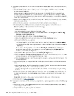
c) Select the appropriate empty NVMe U.2 drive slot from the slots that are listed by the command.
d) Record the slot that you have selected.
e) To prepare the slot to accept an NVMe U.2 drive, complete the following steps:
i) Type the following command:
drmgr -c pci -a -s locationcode
Where
locationcode
is the location of the NVMe slot. For example, the location might be
U78D4.001.AAAXXXX-P2-C1.
ii) Press Enter. A fast-flashing amber LED at the front of the system near where the NVMe slot is
located indicates that the slot is identified.
f) Physically verify that the slot you identified is where you want to install or replace the NVMe U.2
drive.
• Use the blue identify LED on the enclosure to locate the system. Ensure that the serial number
of the system matches the serial number to be serviced.
• Look for a flashing amber LED, which identifies the slot that was selected by using the identify
function.
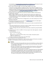
13. Attach the electrostatic discharge (ESD) wrist strap.
The ESD wrist strap must be connected to an unpainted metal surface until the service procedure is
completed, and if applicable, until the service access cover is replaced.
Attention:
• Attach an electrostatic discharge (ESD) wrist strap to the front ESD jack, to the rear ESD jack,
or to an unpainted metal surface of your hardware to prevent the electrostatic discharge
from damaging your hardware.
• When you use an ESD wrist strap, follow all electrical safety procedures. An ESD wrist strap
is used for static control. It does not increase or decrease your risk of receiving electric
shock when using or working on electrical equipment.
• If you do not have an ESD wrist strap, just prior to removing the product from ESD packaging
and installing or replacing hardware, touch an unpainted metal surface of the system for
a minimum of 5 seconds. If at any point in this service process you move away from the
system, it is important to again discharge yourself by touching an unpainted metal surface
for at least 5 seconds before you continue with the service process.
Installing an NVMe U.2 drive in the 9040-MR9 system
To install an NVMe U.2 drive into the system, complete the steps in this procedure.
Procedure
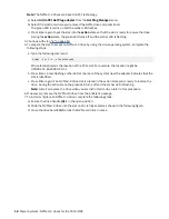
1. Ensure that you have the electrostatic discharge (ESD) wrist strap on and that the ESD clip is plugged
into a ground jack or connected to an unpainted metal surface. If not, do so now.
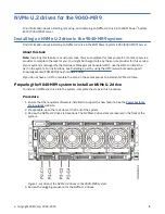
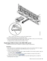
2. Remove the NVMe drive filler from the slot where you want to install the NVMe U.2 drive.
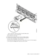
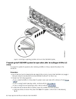
a) Press the filler handle release latch (A) in the direction that is shown to release the handle (B).
b) Slide the filler out of the slot, supporting the bottom and sides.
6 Power Systems: NVMe U.2 drives for the 9040-MR9
Содержание Power System System E950
Страница 1: ...Power Systems NVMe U 2 drives for the 9040 MR9 IBM...
Страница 4: ...iv...
Страница 14: ...xiv Power Systems NVMe U 2 drives for the 9040 MR9...
Страница 18: ...or or or or 4 Power Systems NVMe U 2 drives for the 9040 MR9...
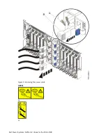
Страница 26: ...Figure 9 Removing the power cords L003 or or 12 Power Systems NVMe U 2 drives for the 9040 MR9...
Страница 44: ...30 Power Systems NVMe U 2 drives for the 9040 MR9...
Страница 55: ......
Страница 56: ...IBM...

