background image

Note:


Before


using


this


information


and


the


product


it


supports,


read


the


general


information


in


Appendix


B,


“IBM


Statement


of


Limited


Warranty


Z125-4753-07


11/2002,”


on


page


79


and


Appendix


C,


“Notices,”


on


page


95.


Third


Edition


(May


2004)


©


Copyright


International


Business


Machines


Corporation


2004.


All


rights


reserved.


US


Government


Users


Restricted


Rights


Use,


duplication


or


disclosure


restricted


by


GSA


ADP


Schedule


Contract


with


IBM


Corp.


Содержание HS40 - BladeCenter - 8839

Страница 1: ...Guide and User s Installation and User s Guide Install and start the blade servers Install addtional applications such as IBM systems management software and IBM ServeRAID programs Server is ready to...

Страница 2: ...r loose connections and verify that all optional devices you installed are on the ServerProven list You can view the ServerProven list at http www ibm com pc compat Server working properly Problem sol...

Страница 3: ...BladeCenter HS40 Type 8839 Installation and User s Guide ERserver...

Страница 4: ...ment of Limited Warranty Z125 4753 07 11 2002 on page 79 and Appendix C Notices on page 95 Third Edition May 2004 Copyright International Business Machines Corporation 2004 All rights reserved US Gove...

Страница 5: ...EDs 18 Chapter 3 Installing options 21 Installation guidelines 21 System reliability considerations 21 Handling static sensitive devices 21 Removing the blade server from the BladeCenter unit 22 Openi...

Страница 6: ...Solving problems 65 Diagnostic tools overview 65 Beep code descriptions 66 POST error messages 67 ServerGuide problems 67 Troubleshooting charts 68 Memory problems 68 Microprocessor problems 68 Monito...

Страница 7: ...pliance statement 98 Australia and New Zealand Class A statement 98 United Kingdom telecommunications safety requirement 98 European Union EMC Directive conformance statement 99 Taiwanese Class A warn...

Страница 8: ...vi BladeCenter HS40 Type 8839 Installation and User s Guide...

Страница 9: ...lleert eerst de veiligheidsvoorschriften Ennen kuin asennat t m n tuotteen lue turvaohjeet kohdasta Safety Information Avant d installer ce produit lisez les consignes de s curit Vor der Installation...

Страница 10: ...ns of the caution or danger statement in the IBM Safety Information book For example if a caution statement begins with a number 1 translations for that caution statement appear in the IBM Safety Info...

Страница 11: ...quipment when there is evidence of fire water or structural damage v Disconnect the attached power cords telecommunications systems networks and modems before you open the device covers unless instruc...

Страница 12: ...DVD drives fiber optic devices or transmitters are installed note the following v Do not remove the covers Removing the covers of the laser product could result in exposure to hazardous laser radiatio...

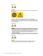
Страница 13: ...power control button on the device and the power switch on the power supply do not turn off the electrical current supplied to the device The device also might have more than one power cord To remove...

Страница 14: ...tatement 13 DANGER Overloading a branch circuit is potentially a fire hazard and a shock hazard under certain conditions To avoid these hazards ensure that your system electrical requirements do not e...

Страница 15: ...d with the Installation and User s Guide are software CDs that help you to configure hardware install device drivers and install the operating system To download the latest device drivers go to the IB...

Страница 16: ...Your BladeCenter HS40 blade server will have one of the bezels shown in the following illustration Release levers Release button A set of user labels comes with the blade server When you install the...

Страница 17: ...ety Information document v BladeCenter HS40 Type 8839 Hardware Maintenance Manual and Troubleshooting Guide This document contains information to help you solve BladeCenter HS40 problems yourself and...

Страница 18: ...rompt on each blade server enabling the blade servers to be managed from a remote location Additional documentation might be included on the IBM BladeCenter Documentation CD or the IBM BladeCenter T D...

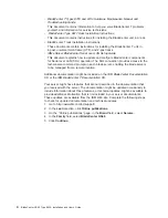
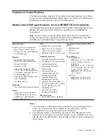
Страница 19: ...ion unit Size v Height 24 5 cm 9 7 inches v Depth 44 6 cm 17 6 inches v Width 5 9 cm 2 32 inches v Maximum weight 7 0 kg 15 4 lb Integrated functions v Four Gigabit Ethernet controllers v ATI Radeon 7...

Страница 20: ...communication with keyboard mouse diskette drive and CD ROM drive2 v Serial over LAN SOL management interface Electrical input v Input power 400 W maximum Predictive Failure Analysis PFA alerts v Micr...

Страница 21: ...the English version is displayed Use one of the following procedures to start the Documentation Browser v If Autostart is enabled insert the CD into your CD ROM drive The Documentation Browser starts...

Страница 22: ...description of a potentially hazardous procedure step or situation v Danger These statements indicate situations that can be potentially lethal or extremely hazardous to you A danger statement is pla...

Страница 23: ...lade server supports serial over LAN SOL technology which provides advanced remote management capability It provides the ability to redirect server serial data over a LAN without the use of serial con...

Страница 24: ...ory v Centrally manage individual or large groups of IBM and non IBM Intel based servers desktop computers workstations and mobile computers on a variety of platforms IBM Director provides a comprehen...

Страница 25: ...http www ibm com servers eserver xseries systems_management xseries_sm html This Web page presents an overview of IBM Systems Management and IBM Director Major components of the BladeCenter HS40 Type...

Страница 26: ...or socket 2 Microprocessor socket 4 Microprocessor socket 1 Flex cable connectors to I O board DIMM socket 8 J9H1 DIMM socket 7 J9G1 DIMM socket 6 J9F1 DIMM socket 5 J9E2 DIMM socket 4 J9E1 DIMM socke...

Страница 27: ...on shows the components on the I O board Flex cable connectors to processor board I O expansion option 2 connectors Blade expansion connector J3A1 J4H1 connector J8H1 connector I O expansion option 1...

Страница 28: ...ows the LEDs on the processor board Microprocessor mismatch error LED DS5H3 Light path diagnostics button SW9J1 Light path diagnostics LED green DS9J1 DIMM 1 error LED DS6C1 DIMM 2 error LED DS6D1 DIM...

Страница 29: ...rimary IDE error LED DS2H1 Secondary IDE error LED DS6H1 Processor board error LED DS8A2 Board error DS7A2 Light path diagnostics button S8A1 NMI error LED DS7A3 Temperature error LED DS7A4 I O board...

Страница 30: ...ear 3 through 5 Off Reserved Jumpers When the BIOS code page jumper J1E2 is moved from pins 1 and 2 to pins 2 and 3 you can start the blade server from a backup BIOS page The default position is pins...

Страница 31: ...to do so v You can turn on the blade server remotely by means of the service processor in the BladeCenter management module v If your operating system supports the Wake on LAN feature and the blade se...

Страница 32: ...on LED CD diskette USB select button CD Keyboard mouse video select button Power control button CD diskette USB select button Press this button to associate the CD ROM drive diskette drive and USB po...

Страница 33: ...h keyboard mouse video control between blade servers NumLock NumLock blade server number Enter where blade server number is the two digit number for the blade bay in which the blade server is installe...

Страница 34: ...f through the BladeCenter management module Web interface or through the IBM Director Console Information LED When this LED is lit it indicates that a noncritical event has occurred The information LE...

Страница 35: ...nts See the instructions for removing or installing a specific hot swap component for any additional procedures that you might have to perform before you remove or install the component v For a list o...

Страница 36: ...setting it down If it is necessary to set the device down place it in its static protective package Do not place the device on your blade server cover or on a metal table v Take additional care when...

Страница 37: ...rn off the blade server See Controls and LEDs on page 18 for more information about the location of the power control button Attention Wait at least 30 seconds until the drives stop spinning before pr...

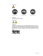
Страница 38: ...en as shown in the illustration 4 Lay the cover flat or lift it from the blade server Statement 21 CAUTION Hazardous energy is present when the blade server is connected to the power source Always rep...

Страница 39: ...server has two connectors on the I O board for installing an optional 2 5 inch HS20 IDE Hard Disk Drive or BladeCenter Flash Disk Drive Each IDE connector is on a separate bus Some models might come...

Страница 40: ...Do not install an IDE drive into IDE connector 2 if you intend to also install an optional I O expansion card The I O expansion card occupies the same area as the second IDE drive 1 Read the safety in...

Страница 41: ...ported for your blade server are 256 MB 512 MB 1 GB and 2 GB Your blade server supports a minimum of 512 MB and a maximum of 16 GB v You might have to enable large memory support for your operating sy...

Страница 42: ...s 3 Carefully lay the blade server on a flat static protective surface 4 Open the blade server cover see Opening the blade server cover on page 24 for instructions and lift it off the blade server 5 P...

Страница 43: ...systems and application programs can distribute the processing load between the microprocessors To use SMP obtain an SMP capable operating system For a list of supported operating systems and other op...

Страница 44: ...cessors 6 Locate the microprocessor socket on the processor board See Processor board components on page 12 for numbering order of processors Note Processors must be installed in order starting with m...

Страница 45: ...he microprocessor in the socket Failure to do so might result in permanent damage to the microprocessor microprocessor socket and processor board Lever closed Lever fully open or Lever closed Lever fu...

Страница 46: ...heat sink on top of the microprocessor Press firmly on the heat sink 11 Lower the retention mechanism then screw down the captive mounting screw using a 2 Phillips screwdriver Do not overtighten the s...

Страница 47: ...u module Because pass thru modules are compatible with a variety of I O expansion cards installing two pass thru modules would allow use of several different types of compatible I O expansion cards wi...

Страница 48: ...ctor J8H1 or connector J4H1 if you are installing an I O expansion card in I O expansion location 2 that secure the I O board to the unit as shown in the illustration 6 Install the I O expansion card...

Страница 49: ...al expansion unit Installing a SCSI storage expansion unit Attention You must install a SCSI storage expansion unit that is specified for use with the BladeCenter HS40 Type 8839 blade server Two types...

Страница 50: ...e illustrations used in this procedure depict the installation process on a BladeCenter HS40 blade server in a BladeCenter Type 8677 unit These illustrations might differ slightly from your hardware 1...

Страница 51: ...ocessor 2 is positioned and pushed down so that both heat sink captive mounting screws are through the holes in the air baffle Air baffle Microprocessor 1 and 4 heat sink captive mounting screws 8 Ins...

Страница 52: ...on No shield Shield Use SCSI storage expansion unit with no shield Do not use SCSI storage expansion with shield a Orient the storage expansion unit as shown in the following illustration Cover pins S...

Страница 53: ...lade and expansion unit into three adjacent BladeCenter unit bays Note When any blade server or option is in blade bay 7 through 14 in the BladeCenter unit or blade bay 5 through 8 in the BladeCenter...

Страница 54: ...ble the SCSI controller in the storage expansion unit See the documentation that comes with the storage expansion unit for information about configuring the storage expansion unit and SCSI hard disk d...

Страница 55: ...drive b Align the hard disk drive assembly with the guide rails in the bay c Gently push the hard disk drive assembly into the bay until the drive stops d Push the tray handle to the closed locked pos...

Страница 56: ...assembly from the bay 5 Within 1 minute install the replacement hard disk drive in the hot swap bay see Installing a SCSI hot swap hard disk drive on page 40 for instructions Replacing the battery IB...

Страница 57: ...re than 100 C 212 F v Repair or disassemble Dispose of the battery as required by local ordinances or regulations Complete the following steps to replace the battery 1 Read the safety information begi...

Страница 58: ...9 Reinsert the blade server into the bay in the BladeCenter unit 10 Turn on the blade server 11 Start the blade server Configuration Setup Utility program and set configuration parameters as needed se...

Страница 59: ...s you will not be able to install the bezel assembly which contains an air filter for the BladeCenter T unit If you require an air filter a filter must be provided on the rack 5 For certain options ru...

Страница 60: ...ection The following illustration shows how to close the blade server cover Blade cover Cover pins Air baffle Complete the following steps to close the blade server cover 1 Read the safety information...

Страница 61: ...o the cover pins at the rear of the blade server as shown in the illustration 6 Pivot the cover to the closed position as shown in the illustration until it clicks into place Installing the blade serv...

Страница 62: ...through 8 in the BladeCenter T unit power modules must be present in all four power bays Attention To help ensure proper cooling performance and system reliability make sure that each of the blade bay...

Страница 63: ...install the bezel assembly on the BladeCenter T unit after you have finished installing the blade servers see the BladeCenter T Types 8720 and 8730 Installation and User s Guide for detailed instructi...

Страница 64: ...sor or if your blade server comes with one microprocessor and you have installed additional microprocessors your blade server might be able to operate as an SMP server You might need to upgrade the op...

Страница 65: ...t utility program on page 56 The following product is available for purchase v IBM Remote Deployment Manager RDM Version 4 11 Update 3 or later You can use the IBM RDM Version 4 11 Update 3 or later t...

Страница 66: ...t setting for the Ethernet controller If you disable a device it cannot be configured and the operating system will not be able to detect it this is equivalent to disconnecting the device If you disab...

Страница 67: ...DIMMs must be installed in the blade server that adhere to the special requirements described in Installing memory modules on page 27 CPU Options Select this choice to enable or disable hyper threadin...

Страница 68: ...Utility program and change the power on password the next time the server is turned on Move the switch back to the previous position after the password is changed See Switches and jumpers on page 16 f...

Страница 69: ...lled hardware options and provides updated device drivers for most adapters and devices v Provides diskette free installation for supported Windows operating systems v Includes an online readme file w...

Страница 70: ...dware and you decide not to use the ServerGuide program to install your operating system complete the following steps to download the latest operating system installation instructions from the IBM Sup...

Страница 71: ...and access to critical server settings v Around the clock access to the blade server even if the server is turned off At some time you might need to flash the service processor to apply the latest fir...

Страница 72: ...ry link is restored the Ethernet traffic switches back to the primary Ethernet controller See your operating system device driver documentation for information about configuring for failover Important...

Страница 73: ...oven list at http www ibm com pc compat For your blade server you must configure IDE RAID in the following areas v In BIOS using the Configuration Setup Utility program and the MegaRAID IDE Setup Util...

Страница 74: ...type of RAID array you are setting up You can also manually configure the RAID array F4 using the MegaRAID IDE Setup Utility program however your blade server supports only RAID level 0 stripe or RAI...

Страница 75: ...4 Press F10 to save the changes and exit the MegaRAID IDE Setup Utility program The blade server restarts automatically Status messages that are displayed during restart indicate status of the RAID a...

Страница 76: ...62 BladeCenter HS40 Type 8839 Installation and User s Guide...

Страница 77: ...e drive The BladeCenter unit uses USB for internal communication with these devices Note Unless otherwise stated references to the BladeCenter unit also apply to the BladeCenter T unit 2 Some operatin...

Страница 78: ...instructions in the documentation that comes with the RDM program To determine if your operating system supports the RDM program or for updated information about RDM and information about purchasing...

Страница 79: ...umentation CD or the IBM BladeCenter T Documentation CD that comes with your blade server for more information v Troubleshooting charts These charts list problem symptoms and steps to correct the prob...

Страница 80: ...t they are installed correctly 2 Turn off the blade server then restart the blade server If the problem remains call for service 7 short and 1 long System memory error Call for service Table 4 BMC bee...

Страница 81: ...ed by your blade server and that they are installed correctly Keyboard interface error 004C Keyboard and keyboard controller v Make sure that the keyboard mouse video select button LED on the front of...

Страница 82: ...charts run the diagnostic programs If you have run the diagnostic test programs or if running the tests does not reveal the problem call for service Memory problems Symptom Suggested action The amoun...

Страница 83: ...sound during POST followed by a blank monitor screen If this occurs and the Boot Fail Count feature in the Start Options of the Configuration Setup Utility program is enabled its default setting you m...

Страница 84: ...tion One or more blade servers are unable to communicate with the network Make sure that v The switch modules for the network interface being used are installed in the correct BladeCenter bays and are...

Страница 85: ...nit is in blade bay 7 through 14 in the BladeCenter unit and blade bay 5 through 8 in the BladeCenter T unit power modules are in all four power bays d The power on LED on the blade server control pan...

Страница 86: ...roblems using the light path diagnostics To locate the component that caused the error locate the lit error LED on that component The following illustration shows the LEDs on the processor board Micro...

Страница 87: ...r from the blade server see Opening the blade server cover on page 24 5 Press and hold the light path diagnostics button on the I O board to relight the I O board LEDs that were lit before you removed...

Страница 88: ...ic LED and you should check the system error log in the BladeCenter management module for information about the error Table 7 I O board light path diagnostics LEDs LED Problem Action Light path diagno...

Страница 89: ...ailable to light the LED Replace the blade server cover and reinsert the blade server in a powered BladeCenter unit then after the blade server has been in the BladeCenter unit for several minutes rem...

Страница 90: ...76 BladeCenter HS40 Type 8839 Installation and User s Guide...

Страница 91: ...your system also describes the diagnostic tests that you can perform Most Eserver systems operating systems and programs come with information that contains troubleshooting procedures and explanations...

Страница 92: ...services go to http www ibm com services or go to http www ibm com planetwide for support telephone numbers In the U S and Canada call 1 800 IBM SERV 1 800 426 7378 Hardware service and support You c...

Страница 93: ...e removal of parts and their return to IBM A part that replaces a removed part will assume the warranty service status of the removed part Unless IBM specifies otherwise these warranties apply only in...

Страница 94: ...rom an IBM Internet Web site or from other electronic media and following the instructions that IBM provides If your problem can be resolved with a Customer Replaceable Unit CRU e g keyboard mouse spe...

Страница 95: ...sit in those cases where IBM is responsible for the transportation charges Neither IBM nor your reseller are responsible for any of your confidential proprietary or personal information contained in a...

Страница 96: ...and obligations are subject to the courts of the country in which you acquired the Machine Part 2 Country unique Terms AMERICAS ARGENTINA Governing Law The following is added after the first sentence...

Страница 97: ...goods are of a kind ordinarily acquired for personal domestic or household use or consumption then none of the limitations in this paragraph apply Governing Law The following replaces laws of the cou...

Страница 98: ...added under this heading Disputes arising out of or in connection with this Statement of Limited Warranty shall be finally settled by arbitration which shall be held in Bangalore India in accordance...

Страница 99: ...MAGES MORAL INCIDENTAL OR INDIRECT DAMAGES FOR ANY ECONOMIC CONSEQUENTIAL DAMAGES OR Arbitration The following is added under this heading Disputes arising out of or in connection with this Statement...

Страница 100: ...or Ukraine you may obtain warranty service for that Machine in any of those countries from either 1 an IBM reseller approved to perform warranty service or 2 from IBM If you purchase a Machine in a Mi...

Страница 101: ...registered office and or commercial site location only are competent 4 in France Algeria Benin Burkina Faso Cameroon Cape Verde Central African Republic Chad Comoros Congo Republic Djibouti Democrati...

Страница 102: ...lsinki will appoint the chairman EUROPEAN UNION EU THE FOLLOWING TERMS APPLY TO ALL EU COUNTRIES Consumers have legal rights under applicable national legislation governing the sale of consumer goods...

Страница 103: ...nternal Code LIC The above limitation shall not apply to damages for bodily injuries including death and damages to real property and tangible personal property for which IBM is legally liable 2 UNDER...

Страница 104: ...Internal Code LIC Applicability of suppliers and resellers unchanged FRANCE Limitation of Liability The following replaces the second sentence of the first paragraph of this section In such instances...

Страница 105: ...tion Except as expressly provided in these terms and conditions all statutory conditions including all warranties implied but without prejudice to the generality of the foregoing all warranties implie...

Страница 106: ...aim from IBM UNITED KINGDOM Limitation of Liability The following replaces the terms of this section in its entirety For the purposes of this section a Default means any act statement omission or negl...

Страница 107: ...arranty Service Worldwide 3 years 1 and 2 See Types of Warranty Service for the legend and explanations of warranty service types A warranty period of 3 years on parts and 1 year on labor means that I...

Страница 108: ...ecifies otherwise the failing Machine suitably packaged to a location IBM designates After IBM has repaired or exchanged the Machine IBM will make it available for your collection or for Mail in Servi...

Страница 109: ...F ANY KIND EITHER EXPRESS OR IMPLIED INCLUDING BUT NOT LIMITED TO THE IMPLIED WARRANTIES OF NON INFRINGEMENT MERCHANTABILITY OR FITNESS FOR A PARTICULAR PURPOSE Some states do not allow disclaimer of...

Страница 110: ...ates other countries or both Microsoft Windows and Windows NT are trademarks of Microsoft Corporation in the United States other countries or both Red Hat the Red Hat Shadow Man logo and all Red Hat b...

Страница 111: ...functionality Product recycling and disposal This unit contains materials such as circuit boards cables electromagnetic compatibility gaskets and connectors which may contain lead and copper beryllium...

Страница 112: ...than recommended cables and connectors or by using other than recommended cables and connectors or by unauthorized changes or modifications to this equipment Unauthorized changes or modifications cou...

Страница 113: ...as been tested and found to comply with the limits for Class A Information Technology Equipment according to CISPR 22 European Standard EN 55022 The limits for Class A equipment were derived for comme...

Страница 114: ...100 BladeCenter HS40 Type 8839 Installation and User s Guide...

Страница 115: ...isable Ethernet 52 Ethernet 57 SCSI 36 40 controller enumeration 58 cover closing 46 removing 24 D danger statements 8 diagnostic tools 65 DIMM See memory module documentation CDs 7 drive hot swap ins...

Страница 116: ...blem 68 specifications 5 6 N NOS installation with ServerGuide 55 without ServerGuide 56 notes 8 notes important 96 notices electronic emission 98 notices continued FCC Class A 98 notices and statemen...

Страница 117: ...atic electricity 21 static sensitive devices handling 21 stopping the blade server 17 switch power on password override 54 symmetric multiprocessing 9 system board LEDs 12 system reliability 21 system...

Страница 118: ...104 BladeCenter HS40 Type 8839 Installation and User s Guide...

Страница 119: ......

Страница 120: ...Part Number 90P3102 Printed in USA 1P P N 90P3102...

Отзывы: