Switches
and
jumpers
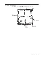
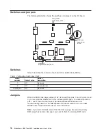
The
following
illustration
shows
the
switches
and
jumpers
on
the
I/O
board.
1
2
3
Configuration
switch block (S6H1)
Light path
diagnostics button (S8A1)
BIOS code
page jumper
(J1E2)
Switches
Table
1
describes
the
function
of
each
switch
on
switch
block
(S6H1).
Table
1.
Configuration
Switch
block
(S6H1)
Switch
number
Default
value
Switch
description
1
Off
Reserved
2
Off
Password
clear
3
through
5
Off
Reserved
Jumpers
When
the
BIOS
code
page
jumper
(J1E2)
is
moved
from
pins
1
and
2
to
pins
2
and
3,
you
can
start
the
blade
server
from
a
backup
BIOS
page.
The
default
position
is
pins
1
and
2.
See
the
blade
server
Hardware
Maintenance
Manual
and
Troubleshooting
Guide
on
the
IBM
BladeCenter
Documentation
CD
or
the
IBM
BladeCenter
T
Documentation
CD
for
more
information.
Note:
If
you
start
the
blade
server
from
the
backup
page
because
the
primary
BIOS
page
has
become
damaged,
you
need
to
flash
the
primary
BIOS
code.
16
BladeCenter
HS40
Type
8839:
Installation
and
User’s
Guide
Содержание HS40 - BladeCenter - 8839
Страница 3: ...BladeCenter HS40 Type 8839 Installation and User s Guide ERserver...
Страница 8: ...vi BladeCenter HS40 Type 8839 Installation and User s Guide...
Страница 76: ...62 BladeCenter HS40 Type 8839 Installation and User s Guide...
Страница 90: ...76 BladeCenter HS40 Type 8839 Installation and User s Guide...
Страница 114: ...100 BladeCenter HS40 Type 8839 Installation and User s Guide...
Страница 118: ...104 BladeCenter HS40 Type 8839 Installation and User s Guide...
Страница 119: ......
Страница 120: ...Part Number 90P3102 Printed in USA 1P P N 90P3102...

