background image

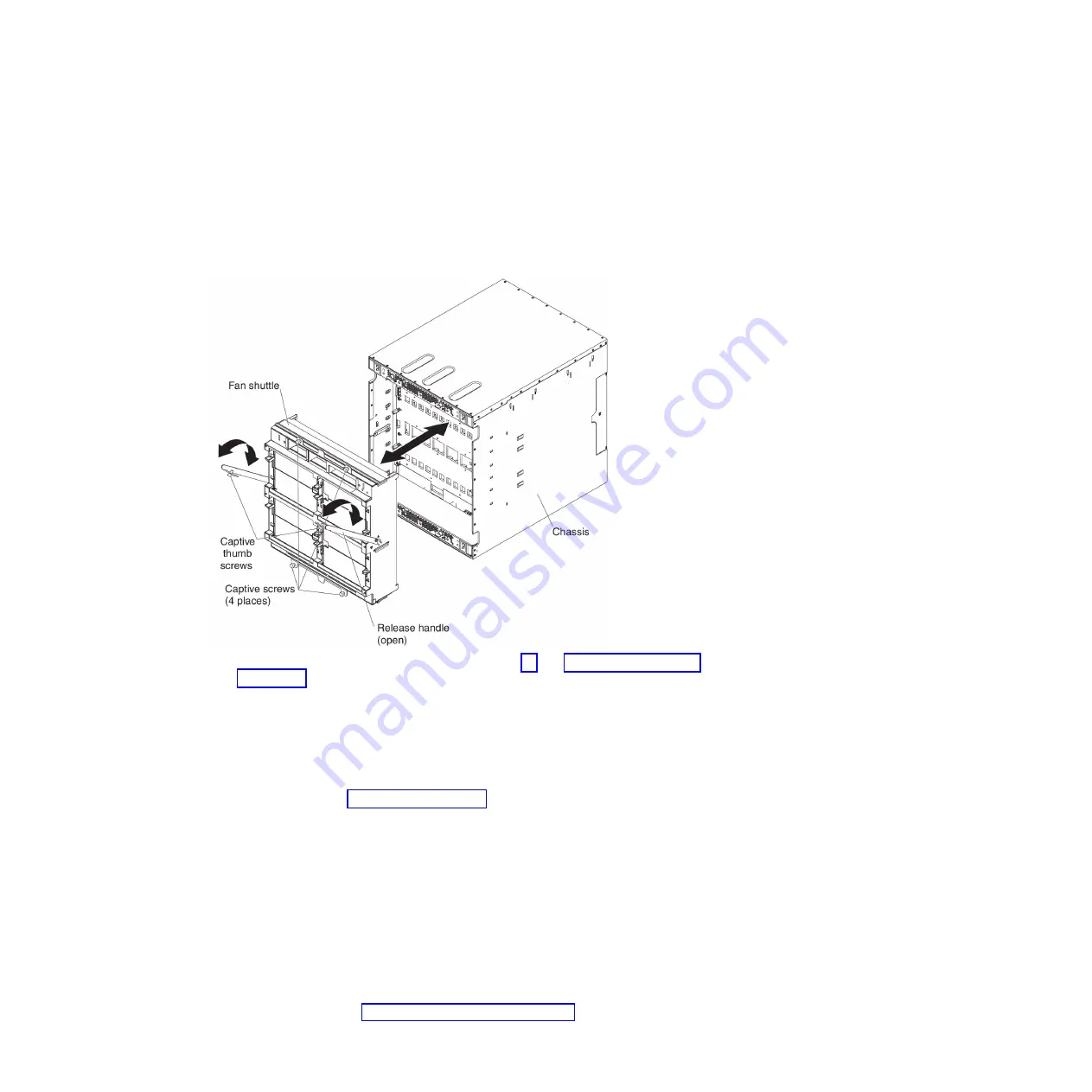
9. While you support the fan shuttle with your hands, pull the shuttle out of the

BladeCenter HT chassis.

10. If you are instructed to return the shuttle, follow all packaging instructions and

use any packaging materials for shipping that are supplied to you.

Installing the fan shuttle

To install the shuttle, complete the following steps.

1. Read the safety information that begins on page vii and “Installation guidelines”

on page 31.

2. Make sure that no modules are installed in the fan shuttle and the release

handles on the shuttle are in the open position.

Attention:

Use your hands to hold the frame of the fan shuttle where the

fan-module bays are located. Do not use the release handles to hold the fan
shuttle.

3. Orient the fan shuttle so that fan-module bays 1 and 3 are above fan-module

bays 2 and 4 (see “Rear view” on page 16).

4. Align the shuttle with the BladeCenter chassis and push the shuttle into the

chassis until it stops.

5. Push the release handles to the closed position. The shuttle will move back

fully into the BladeCenter chassis.

6. Tighten the captive thumbscrews on the fan shuttle.

7. Tighten the captive thumbscrew on each release handle.

Important:

The release handles have a safety switch that disables power

output from the power boxes. If the release handles are not secured to the
chassis with the thumbscrews, the BladeCenter HT unit will not power on.

8. Install any of the following modules that were removed from the rear of the

BladeCenter HT unit:

v

Fan modules (see “Installing a fan module” on page 85).

90

BladeCenter HT Type 8740 and 8750: Problem Determination and Service Guide

Содержание BladeCenter HT 8740

Страница 1: ...BladeCenter HT Type 8740 and 8750 Problem Determination and Service Guide ...

Страница 2: ......

Страница 3: ...BladeCenter HT Type 8740 and 8750 Problem Determination and Service Guide ...

Страница 4: ...IBM Systems Environmental Notices and User Guide documents on the IBM Documentation CD The most recent version of this document is available at http www ibm com systems supportportal Fifth Edition October 2012 Copyright IBM Corporation 2012 US Government Users Restricted Rights Use duplication or disclosure restricted by GSA ADP Schedule Contract with IBM Corp ...

Страница 5: ...iguring blade servers 22 BladeCenter networking guidelines 22 Chapter 3 Parts listing 23 Front view 24 Rear view 26 AC power cords 28 Chapter 4 Removing and replacing BladeCenter HT components 31 Installation guidelines 31 System reliability guidelines 32 Handling static sensitive devices 32 Returning a device or component 33 Removing and replacing Tier 1 CRUs 34 Removing a bezel 34 Installing a b...

Страница 6: ...n module 83 Installing a fan module 85 Removing a dc terminal cover 86 Installing a dc terminal cover 88 Removing the fan shuttle 89 Installing the fan shuttle 90 Removing and replacing FRUs 92 Removing a power box 92 Installing a power box 94 Removing the midplane 96 Installing the midplane 98 Chapter 5 Diagnostics 101 Diagnostic tools 101 Troubleshooting tables 102 Blade server problems 102 Fan ...

Страница 7: ...tatement 128 Industry Canada Class A emission compliance statement 128 Avis de conformité à la réglementation d Industrie Canada 128 Australia and New Zealand Class A statement 129 European Union EMC Directive conformance statement 129 Germany Class A statement 129 VCCI Class A statement 130 Japan Electronics and Information Technology Industries Association JEITA statement 130 Korea Communication...

Страница 8: ...vi BladeCenter HT Type 8740 and 8750 Problem Determination and Service Guide ...

Страница 9: ...fety Information Avant d installer ce produit lisez les consignes de sécurité Vor der Installation dieses Produkts die Sicherheitshinweise lesen Prima di installare questo prodotto leggere le Informazioni sulla Sicurezza Les sikkerhetsinformasjonen Safety Information før du installerer dette produktet Antes de instalar este produto leia as Informações sobre Segurança Antes de instalar este product...

Страница 10: ...an cause serious or fatal electrical shock v Explosive hazards such as a damaged CRT face or a bulging capacitor v Mechanical hazards such as loose or missing hardware To inspect the product for potential unsafe conditions complete the following steps 1 Make sure that the power is off and the power cords are disconnected 2 Make sure that the exterior cover is not damaged loose or broken and observ...

Страница 11: ... Disconnect all power before you perform a mechanical inspection work near power supplies or remove or install main units v Before you work on the equipment disconnect all power cords If you cannot disconnect the power cords have the customer power off the wall box that supplies power to the equipment and lock the wall box in the off position v Never assume that power has been disconnected from a ...

Страница 12: ...cument For example if a caution statement is labeled Statement 1 translations for that caution statement are in the Safety Information document under Statement 1 Be sure to read all caution and danger statements in this document before you perform the procedures Read any additional safety information that comes with the server or optional device before you install the device x BladeCenter HT Type ...

Страница 13: ...nces or regulations Statement 3 CAUTION When laser products such as CD ROMs DVD drives fiber optic devices or transmitters are installed note the following v Do not remove the covers Removing the covers of the laser product could result in exposure to hazardous laser radiation There are no serviceable parts inside the device v Use of controls or adjustments or performance of procedures other than ...

Страница 14: ...arts contact a service technician Statement 12 CAUTION The following label indicates a hot surface nearby Statement 13 DANGER Overloading a branch circuit is potentially a fire hazard and a shock hazard under certain conditions To avoid these hazards ensure that your system electrical requirements do not exceed branch circuit protection requirements Refer to the information that is provided with y...

Страница 15: ... bonding jumper from an earthing terminal bar or bus to which the dc supply system earthing electrode conductor is connected v This equipment shall be located in the same immediate area such as adjacent cabinets as any other equipment that has a connection between the earthed conductor of the same dc supply circuit and the earthing conductor and also the point of earthing of the dc system The dc s...

Страница 16: ...edures v Connect and disconnect cables as described in the following table when installing moving or opening covers on this product or attached devices To Connect To Disconnect 1 Turn OFF all power sources and equipment to be attached to this product 2 Attach all cables to the devices 3 Attach signal cables to the connectors 4 Attach power cords to power sources For dc systems ensure correct polar...

Страница 17: ...not provide a power control button Removing power supply modules or turning off the server blades does not turn off the electrical current supplied to the device The device also might have more than one power cord To remove all electrical current from the device ensure that all power cords are disconnected from the power source BladeCenter HT Type 8740 BladeCenter HT Type 8750 Safety xv ...

Страница 18: ...rmal and single fault conditions do not cause the voltages to exceed a safe level 60 V direct current v Incorporate a readily available approved and rated disconnect device in the field wiring v See the specifications in the product documentation for the required circuit breaker rating for branch circuit overcurrent protection v Use copper wire conductors only See the specifications in the product...

Страница 19: ...ns instructions for setting up the BladeCenter HT unit and general information about the BladeCenter HT unit including information about features and how to configure the BladeCenter HT unit It also contains detailed instructions for installing removing and connecting optional devices that the BladeCenter HT unit supports v BladeCenter HT 2 Post Rack Installation Instructions This document is in P...

Страница 20: ...T DC Power Supply Modules Installation Instructions This document provides the installation instructions and warranty information for an IBM BladeCenter HT dc Power Supply Module v IBM BladeCenter HT Interposer for Gb Switch Bridge Bays and IBM BladeCenter HT Interposer for Gb Switch Bridge Bays with Interswitch Links ISL Installation Instructions This document provides the installation instructio...

Страница 21: ... statement is placed just before the description of a potentially lethal or extremely hazardous procedure step or situation Deployment scenarios The IBM BladeCenter HT unit can be deployed to support a variety of networking goals and environments such as v Central Office CO environment IBM BladeCenter HT is ideally suited for network telecommunications facilities or carrier grade environments that...

Страница 22: ...clustered solutions to achieve significantly higher degrees of scalability and performance all managed at a low cost v Any location where the National Electric Code NEC applies The IBM BladeCenter HT unit can be installed in any location where NEC requirements are used 4 BladeCenter HT Type 8740 and 8750 Problem Determination and Service Guide ...

Страница 23: ... optional bezel 617 mm 24 29 in With optional bezel 706 mm 27 80 in v Width 442 mm 17 4 in v Weight Full configured weight with blade servers Approximately 158 8 kg 350 lb Empty chassis without modules or blade servers Approximately 65 32 kg 144 lb Environment per Telcordia GR 63 CORE v Operational Altitude 60 m to 1800 m 197 ft to 6000 ft 5 C to 40 C 41 F to 104 F Altitude 1800 m to 4000 m 6000 f...

Страница 24: ...dule bay 1 power connector 2 bottom left connector supplies power to power module 2 power connector 3 top left connector supplies power to power module 3 and power connector 4 bottom right connector supplies power to power module 4 Physical view Power modules 1 and 2 are redundant and provide power to blade bays 1 through 6 power modules 3 and 4 are redundant and provide power to blade bays 7 thro...

Страница 25: ...d to the equipment frame or the grounding means of the equipment Attention Only trained service personnel other than IBM service technicians are authorized to make the connections to and disconnections from the 48 volt dc power source IBM service technicians are not certified or authorized to install or remove the 48 volt power cable The customer is responsible for ensuring that only trained servi...

Страница 26: ... of manufacture The following illustrations show both types of terminal boxes for the two types of terminal covers When connecting a wire to each stud install a flat washer optional on the stud install the wire install a flat washer optional install a split washer and then install the nut The following guidelines are provided for connecting a 60 A BladeCenter HT unit to a 48 V dc power source v Th...

Страница 27: ...be determined by the current draw and the length of wire run or as specified by the customer premises guidelines v Flexible dc wiring is recommended to allow for minimum bend radius v The supply wiring to the power connectors must be terminated in UL recognized insulated ring terminals sized for a M6 stud 4 AWG wire circular mil area of 33100 52600 and a wire insulation diameter of 12 8 to 13 1 mm...

Страница 28: ...eCenter HT unit has four ac power C20 input connectors Two C20 C19 type ac jumper cords are supplied with the BladeCenter HT unit To supply power to the BladeCenter HT unit connect one end of each power cord to a power connector on the rear of the BladeCenter HT unit and the other end of each power cord to a 200 240 volt 20 amp power distribution unit or appropriate electrical outlet An external S...

Страница 29: ...vice does not provide a power control button Removing power supply modules or turning off the server blades does not turn off the electrical current supplied to the device The device also might have more than one power cord To remove all electrical current from the device ensure that all power cords are disconnected from the power source Attention Only trained service personnel other than IBM serv...

Страница 30: ...d Remove the nut split washer flat washer and power cord from each terminal post e Remove the power cables 12 BladeCenter HT Type 8740 and 8750 Problem Determination and Service Guide ...

Страница 31: ...es or turning off the server blades does not turn off the electrical current supplied to the device The device also might have more than one power cord To remove all electrical current from the device ensure that all power cords are disconnected from the power source b Disconnect all power cords on the BladeCenter HT unit from the power connectors Chapter 1 Introduction 13 ...

Страница 32: ... power module indicate the condition of the power module and fan pack Note The orientation of the power module shown in the illustration is for one of the top power modules The orientation for modules in the bottom power module bays is rotated 180 v Input power LED When this green LED is lit the input from the external power source connected to the power module is present and within specifications...

Страница 33: ...ctive To remove all electrical current from the BladeCenter HT unit you must disconnect all power cords from all power input connectors Location When this blue LED is lit or flashing it has been turned on by the system administrator to aid in visually locating the BladeCenter HT unit If a blade server requires attention the location LED on the blade server usually will also be lit After the BladeC...

Страница 34: ...The system can continue to operate usually without the use of the components on the media tray USB connectors Use these connectors to attach USB v2 0 or earlier compatible devices with 2 5 m 8 2 ft cables Rear view This section identifies the components connectors and LEDs on the rear of the BladeCenter HT unit The following illustration shows a BladeCenter HT Type 8740 with dc power connections 1...

Страница 35: ...enter HT unit has four power connectors For information on power source requirements and cabling for your BladeCenter HT unit see Supplying power to the BladeCenter HT unit on page 6 for more information Chapter 1 Introduction 17 ...

Страница 36: ...t on each blade server v Power on When this green LED is lit power is present in the BladeCenter HT unit When this LED is off the power subsystem the power module or the LED has failed Attention If the power on LED is off it does not mean that no electrical current is present in the BladeCenter HT unit The LED might be defective To remove all electrical current from the BladeCenter HT unit you mus...

Страница 37: ...s blue LED is lit it is safe to remove the device from the BladeCenter HT unit v Alarm panel module fault When this amber LED is lit there is a fault on the alarm panel module The system can continue to operate usually without the use of the components on the alarm panel module v Serial connector This DB60 connector provides direct access to the serial ports on each of the 12 blade server bays Use...

Страница 38: ...here are two information LEDs on the multiplexer expansion module v FRU ready for removal When this blue LED is lit it is safe to remove the device from the BladeCenter HT unit Under normal conditions the blue FRR LED on the multiplexer expansion module that is associated with the active management module is off and the blue FRR LED on the multiplexer expansion module that is associated with the s...

Страница 39: ...are preconfigured with the same static IP address You can use the management module to assign a new static IP address To establish connectivity the management module attempts to use Dynamic Host Control Protocol DHCP to acquire its initial IP address for the management module Ethernet port If DHCP is not installed or is enabled and fails the management module uses the static IP address Use the man...

Страница 40: ... configured before you connect the BladeCenter HT unit to a LAN switch or similar network device Each blade server has two independent Ethernet controllers each with its own MAC address and a dedicated 1000 Mbps link to one of the switch modules in I O module bays 1 and 2 Switches that support Inter Switch Link ISL can be configured to support switch to switch traffic on up to two internal switch ...

Страница 41: ...ls a Tier 1 CRU at your request you will be charged for the installation v Tier 2 customer replaceable unit You may install a Tier 2 CRU yourself or request IBM to install it at no additional charge under the type of warranty service that is designated for your server v Field replaceable unit FRU FRUs must be installed only by trained service technicians For information about the terms of the warr...

Страница 42: ... Filler advanced management module and I O module use with 42C3070 42C3068 5 dc power module without fan pack 39Y7370 ac power module without fan pack 39Y7374 6 Filler power module 42C3079 7 Fan pack 31R3302 8 Advanced management module interposer 42C3098 9 Advanced management module 39Y9661 10 Filler advanced management module and I O module use with 42C3070 42C3068 24 BladeCenter HT Type 8740 an...

Страница 43: ...3078 High speed I O interposer tray bottom 42C3084 17 Filler high speed I O module double 42C3072 18 Filler blade server 39M3317 Bezel assembly with filter and collar 42C3696 Cable management tray top 42C3736 Cable management tray bottom 42C3737 Chassis lift handles 4 42C3733 System service card 42C3729 Air filter 42C3739 Cisco Systems 4X InfiniBand Switch Module for IBM BladeCenter 23E1756 Switch...

Страница 44: ...23 6 Alarm panel module 42C3726 7 Network clock filler 42C3680 8 ac power box top 42C2962 ac power box bottom 42C3007 9 dc power box top 42C2938 9 dc power box with cover top 44T2260 9 dc power box bottom 42C2941 9 dc power box with cover bottom 44T2261 10 dc terminal cover with fasteners 4 42C3076 10 dc terminal cover for 44T2260 and 44T2261 44T2259 26 BladeCenter HT Type 8740 and 8750 Problem De...

Страница 45: ...scription CRU part number Tier 1 CRU part number Tier 2 FRU part number Cable alarm panel 15 pin cable 39M4255 Cable ac jumper cord C20 C19 39M5456 Cable serial port breakout 40K9608 Chapter 3 Parts listing 27 ...

Страница 46: ...atia Republic of Czech Rep Dahomey Djibouti Egypt Equatorial Guinea Eritrea Estonia Ethiopia Finland France French Guyana French Polynesia Gabon Georgia Germany Greece Guadeloupe Guinea Guinea Bissau Hungary Iceland Indonesia Iran Kazakhstan Kyrgyzstan Laos Peoples Democratic Republic of Latvia Lebanon Lithuania Luxembourg Macedonia former Yugoslav Republic of Madagascar Mali Martinique Mauritania...

Страница 47: ...ia Liechtenstein Malawi Malaysia Malta Myanmar Burma Nigeria Oman Qatar Saint Kitts Nevis Saint Lucia Saint Vincent and the Grenadines Seychelles Sierra Leone Singapore Sudan Tanzania United Republic of Trinidad Tobago United Arab Emirates Dubai United Kingdom Yemen Zambia Zimbabwe Uganda 39M5330 Cable AS NZS 3112 Australia Fiji Kiribati Nauru New Zealand Papua New Guinea 39M5342 Cable IRAM 2073 A...

Страница 48: ...30 BladeCenter HT Type 8740 and 8750 Problem Determination and Service Guide ...

Страница 49: ... or replace any of the hot swap modules in the BladeCenter HT unit You must shut down the operating system and turn off a blade server before you remove the blade server but you do not have to remove power from the BladeCenter HT unit itself v Do not attempt to lift an object that you think is too heavy for you If you have to lift a heavy object observe the following precautions Make sure that you...

Страница 50: ...avoid damage keep static sensitive devices in their static protective packages until you are ready to install them Electrostatic discharge ESD is the release of stored static electricity that can damage electric circuits Static electricity is often stored in your body and discharged when you come in contact with an object with a different potential Use an ESD wrist strap and the ESD connectors on ...

Страница 51: ...d install it immediately without setting down the device If it is necessary to set down the device put it back into its static protective package v Take additional care when handling devices during cold weather Heating reduces indoor humidity and increases static electricity Returning a device or component If you are instructed to return a device or component follow all packaging instructions and ...

Страница 52: ...ny devices installed into the front of your BladeCenter HT unit To remove the bezel complete the following steps 1 Read the safety information that begins on page vii and Installation guidelines on page 31 2 Use your hands to hold the bezel and press the blue release button on each side of the bezel 3 Pull the bezel away from the BladeCenter HT unit 4 If you are instructed to return the bezel foll...

Страница 53: ...ing the sides of the bezel orient the bezel so the IBM logo is at the top and right corner 3 Place the bottom edge of the bezel on the bezel retention tab 4 Rotate the top of the bezel toward the BladeCenter HT unit until the bezel clicks into place 5 Turn the quarter turn bezel locks to the locked position Chapter 4 Removing and replacing BladeCenter HT components 35 ...

Страница 54: ...he bezel see Removing a bezel on page 34 3 Lay the bezel on a flat work surface and orient it so that the bottom of the bezel is closest to you and the light path holes are to the right The large rectangles in the filter frame should be closest to you 36 BladeCenter HT Type 8740 and 8750 Problem Determination and Service Guide ...

Страница 55: ...ing out and rotating the air filter assembly locks until they no longer engage the air filter assembly 5 Remove the air filter assembly then remove the old filter from the filter frame and dispose of it Chapter 4 Removing and replacing BladeCenter HT components 37 ...

Страница 56: ...lines on page 31 2 Lay the bezel on a flat work surface and orient it so that the bottom of the bezel is closest to you and the light path holes are to the right The large rectangles in the filter frame should be closest to you 38 BladeCenter HT Type 8740 and 8750 Problem Determination and Service Guide ...

Страница 57: ... assemblies are to the right and the large cutout at the bottom of the filter is closest to you 4 Orient the filter frame to the filter and place the filter frame on top of the filter then pick up the filter assembly and install it into the bezel Chapter 4 Removing and replacing BladeCenter HT components 39 ...

Страница 58: ...out and rotating the air filter assembly locks until they engage the air filter assembly 6 Install the bezel on the BladeCenter HT unit see Installing a bezel on page 35 40 BladeCenter HT Type 8740 and 8750 Problem Determination and Service Guide ...

Страница 59: ...e Removing a bezel on page 34 for more information 3 Remove the light path extension assembly Two light path extension assemblies are shipped with theBladeCenter HT Bezel to extend the light path LEDs so that they are visible through the bezel Remove one light path extension assembly for each of the media trays installed in your BladeCenter HT unit Chapter 4 Removing and replacing BladeCenter HT c...

Страница 60: ... management module bay 1 See Removing a management module on page 75 and Removing a management module interposer on page 73 for more information d Remove any I O modules and their interposer trays from I O bays 7 and 8 See Removing an I O module on page 64 and Removing an I O module interposer on page 62 for more information 42 BladeCenter HT Type 8740 and 8750 Problem Determination and Service Gu...

Страница 61: ... management trays so that they do not secure the trays and bezel collar to the BladeCenter HT unit f Remove the bezel collar by lifting up the bezel collar and then pulling the bezel collar away from the BladeCenter HT unit Chapter 4 Removing and replacing BladeCenter HT components 43 ...

Страница 62: ... are used to secure the upper cable management tray and four M4 screws are used to secure the lower cable management tray 5 If you are instructed to return the bezel collar follow all packaging instructions and use any packaging materials for shipping that are supplied to you 44 BladeCenter HT Type 8740 and 8750 Problem Determination and Service Guide ...

Страница 63: ...s on page 31 2 If installed remove the cable management trays from the BladeCenter HT unit See Removing a cable management tray on page 49 for more information 3 Attach the cable management trays to the bezel collar a Position the bezel collar so that the light path extension assembly retention tabs are on your left Chapter 4 Removing and replacing BladeCenter HT components 45 ...

Страница 64: ...ing a management module on page 75 and Removing a management module interposer on page 73 for more information 5 Remove any I O modules and their interposer trays from I O bays 7 and 8 See Removing an I O module on page 64 and Removing an I O module interposer on page 62 for more information 6 Attach the bezel collar to the BladeCenter unit a Insert the lower bezel collar hooks into the bezel moun...

Страница 65: ...agement module bay 1 See Installing a management module interposer on page 74 and Installing a management module on page 76 for more information 8 Reinstall any high speed switches and their interposer trays into I O bays 7 and 8 See Installing a high speed I O module interposer tray on page 67 and Installing a high speed I O module on page 72 for more information Chapter 4 Removing and replacing ...

Страница 66: ...y onto the bezel collar in front of the retention tabs The release tab should extend slightly beyond the edge of the collar b Push the assembly toward the back of the collar until the release tab clicks into place While pushing the assembly toward the BladeCenter HT unit ensure that the locator pin is inserted into the hex locator hole to the right of the light path LEDs on the media tray 10 Insta...

Страница 67: ...t begins on page vii and Installation guidelines on page 31 2 Hold the cable management tray with one hand and use a phillips head screwdriver to loosen the captured thumbscrews that attach the cable management tray to the BladeCenter HT unit 3 Pull the cable management tray away from the BladeCenter HT unit 4 Repeat these steps for the other cable management tray 5 If you are instructed to return...

Страница 68: ...per cable management tray so that the captive thumbscrews are positioned towards the blade server bays b Align the captive thumbscrews with the screw holes above I O module bays 1 and 3 c Use a phillips head screwdriver to screw the captured thumbscrews into the BladeCenter HT unit 3 To install the lower cable management tray on the BladeCenter HT complete the following steps a Orient the lower ca...

Страница 69: ...edia tray release handle to the open position The media tray moves out of the bay approximately 0 6 cm 0 25 inch 4 Slide the media tray out of the bay 5 If you are instructed to return the media tray follow all packaging instructions and use any packaging materials for shipping that are supplied to you Note If a CompactFlash module is installed in the media tray remove it from the old media tray a...

Страница 70: ... CompactFlash release button is pressed into the in position 3 Make sure that the media tray release lever is in the open position and the CompactFlash release buttons are pushed in 4 Slide the media tray into position until it stops and locks into place 5 Rotate the media tray release lever to the closed position 52 BladeCenter HT Type 8740 and 8750 Problem Determination and Service Guide ...

Страница 71: ...age 51 3 Press the release button next to the CompactFlash module you are removing The release button extends from the media tray 4 Press the release button again to eject the CompactFlash module from the media tray 5 Press the release button again to return the release button into the in position 6 If you are instructed to return the CompactFlash module follow all packaging instructions and use a...

Страница 72: ...ed remove it see Removing a CompactFlash module on page 53 4 Make sure the CompactFlash release buttons are pushed in 5 Insert the CompactFlash module into the socket on the media tray Note The sides of the CompactFlash card have a guide slot Insert the CompactFlash module with the narrow guide slot positioned towards the front of the media tray 6 Install the media tray into the BladeCenter HT uni...

Страница 73: ...s before you proceed See the documentation that comes with the blade server for instructions for shutting down the blade server operating system and turning off the blade server Statement 8 CAUTION Never remove the cover on a power supply or any part that has the following label attached Hazardous voltage current and energy levels are present inside any component that has this label attached There...

Страница 74: ...up to the open position v For a power module in one of the lower power module bays push the inner handle release to the left then pull the handle down to the open position The power module moves out of the bay approximately 0 6 cm 0 25 inch 4 Use the handle to pull the module out of the bay Within 1 minute install either another power module or a filler into the module bay 5 If you are replacing t...

Страница 75: ...9 3 Make sure that the handle on the power module is in the open position 4 Orient the new power module to the selected power module bay v For the upper power module bays the rear connector on the power module must be facing down v For the lower power module bays the rear connector on the power module must be facing up 5 Slide the module into the bay until it stops then push the handle to the clos...

Страница 76: ...3 With the power module rear connector facing up rotate the handle down so that it is parallel with the bottom of the module 4 Press the blue release tabs on each side of the fan pack 5 Pull the fan pack away from the power module 6 If you are instructed to return the fan pack follow all packaging instructions and use any packaging materials for shipping that are supplied to you 58 BladeCenter HT ...

Страница 77: ... the handle is rotated down so that it is parallel with the bottom of the module with the power module rear connector facing up 3 Slide the fan pack into position on the power module until it stops and locks into place 4 Rotate the power module handle to the open position 5 Install the power module see Installing a power module on page 57 Chapter 4 Removing and replacing BladeCenter HT components ...

Страница 78: ...2 Remove the bezel as needed to access the blade server to be removed see Removing a bezel collar on page 41 3 Shut down the blade server operating system then shut down the blade server See the documentation that comes with your blade servers for the procedure to shut down the operating system Wait at least 30 seconds until the drives stop spinning before you proceed to the next step 4 Pull the t...

Страница 79: ...er in the BladeCenter HT unit you must configure the blade server with the blade server Configuration Setup Utility program and install the blade server operating system See the documentation that comes with the blade server for instructions To install a blade server complete the following steps Note These instructions assume that the BladeCenter HT unit is connected to power 1 Read the safety inf...

Страница 80: ...ls that come with the blade server then place the label on the BladeCenter HT unit top bezel just above the blade server Important Do not place the label on the blade server or in any way block the ventilation holes on the BladeCenter HT unit bezel 9 Install the bezel that was removed during the removal procedure see Installing a bezel collar on page 45 Removing an I O module interposer To remove ...

Страница 81: ...nstall an I O module interposer or interposer tray complete the following steps 1 Read the safety information that begins on page vii and Installation guidelines on page 31 2 Make sure that the I O module interposer release handle or handles are in the open position 3 Slide the interposer into the module bay until it stops 4 Push the release handle or handles to the closed position 5 Install an I ...

Страница 82: ...e Removing a bezel collar on page 41 3 Disconnect all cables from the module 4 Pull the release handle or handles to the open position The module moves out of the bay approximately 0 6 cm 0 25 inch 5 Slide the module out of the bay Within 1 minute install either another module or a filler into the module bay 6 If you are instructed to return the I O module follow all packaging instructions and use...

Страница 83: ...all an I O module or filler complete the following steps 1 Read the safety information that begins on page vii and Installation guidelines on page 31 2 Install the I O module interposer Installing an I O module interposer on page 63 3 Make sure that the I O module release handle or handles are in the open position 4 Slide the module into the module bay until it stops 5 Push the release handle or h...

Страница 84: ...If an I O module or filler is installed in the I O bay remove it see Removing a high speed I O module on page 71 4 Make sure that the I O module interposer release handle is in the open position 5 Pull the release handle to the open position The module moves out of the bay approximately 0 6 cm 0 25 inch 6 Slide the module out of the bay 7 If you are instructed to return the interposer follow all p...

Страница 85: ...i and Installation guidelines on page 31 2 Make sure that the high speed I O module interposer release handles are in the open position 3 Slide the interposer into the module bay until it stops 4 Push the release handles to the closed position 5 Install a high speed I O module or filler see Installing a high speed I O module on page 72 Chapter 4 Removing and replacing BladeCenter HT components 67 ...

Страница 86: ...rposer consists of an interposer tray and an interposer card Orient the I O module interposer so the interposer card is visible 4 Remove the five thumbscrews that secure the interposer card to the interposer tray 5 Use your hand to grab the edges of the interposer card and lift it off the interposer tray 6 If you are instructed to return the interposer follow all packaging instructions and use any...

Страница 87: ...s on page 31 2 Orient the interposer tray so that the standoffs are facing up and place it on a flat surface 3 Orient the interposer card so that the cut out on the edge of the interposer card is at the rear of the tray 4 Mount the high speed interposer card on the tray Chapter 4 Removing and replacing BladeCenter HT components 69 ...

Страница 88: ...rposer card on the lower interposer tray 1 Be sure that the connectors on the interposer card are facing up the opposite of what it is in the illustration above 2 Align the holes in the interposer card with the standoffs on the tray then secure the card to the tray using the supplied thumbscrews 5 Install the high speed I O module interposer into the BladeCenter HT unit see Installing a high speed...

Страница 89: ... collar on page 41 3 Disconnect all cables from the module 4 Pull the release handles to the open position The module moves out of the bay approximately 0 6 cm 0 25 inch 5 Slide the module out of the bay Within 1 minute install either another module or a filler into the module bay 6 If you are instructed to return the high speed I O module follow all packaging instructions and use any packaging ma...

Страница 90: ... speed I O module or filler complete the following steps 1 Read the safety information that begins on page vii and Installation guidelines on page 31 2 Install the high speed I O module interposer See Installing a high speed I O module interposer tray on page 67 for more information 3 Make sure that the high speed I O module release handles are in the open position 4 Slide the module into the modu...

Страница 91: ...filler is installed in the management module bay remove it see Removing a management module on page 75 4 Pull the management module interposer release handle to the open position The interposer moves out of the bay approximately 0 6 cm 0 25 inch 5 Pull the interposer out of the bay Within 1 minute install either another module or a filler into the module bay 6 If you are instructed to return the i...

Страница 92: ...oving a management module on page 75 and Removing a management module interposer on page 73 3 Make sure that the management module interposer release handle is in the open position 4 Slide the interposer into the management module bay 5 Push the release handle on the interposer to the closed position 6 Install a management module or filler into the management module bay see Installing a management...

Страница 93: ...undant management module needs the time to receive initial status information and firmware levels from the primary management module 1 Read the safety information that begins on page vii and Installation guidelines on page 31 2 Remove the bezel if installed to access the management module to be removed see Removing a bezel collar on page 41 3 Disconnect all cables from the module 4 Pull the releas...

Страница 94: ...tops 5 Push the release handle to the closed position 6 Reconnect all cables to the module 7 If this is the only management module in the BladeCenter HT unit restore the configuration from the configuration file that you saved when you removed the old management module See the BladeCenter Management Module User s Guide and the BladeCenter Management Module Command Line Interface Reference Guide fo...

Страница 95: ... to the open position The module moves out of the bay approximately 0 6 cm 0 25 inch 3 Slide the filler out of the bay Within 1 minute install either another module or a filler into the module bay 4 If you are instructed to return the network clock module filler follow all packaging instructions and use any packaging materials for shipping that are supplied to you Chapter 4 Removing and replacing ...

Страница 96: ... information that begins on page vii and Installation guidelines on page 31 2 Make sure that the release handle on the filler is in the open position 3 Slide the module into the module bay until it stops 4 Push the release handle to the closed position 78 BladeCenter HT Type 8740 and 8750 Problem Determination and Service Guide ...

Страница 97: ... information see BladeCenter HT components controls and LEDs on page 14 3 Pull the release handle or handles to the open position The module moves out of the bay approximately 0 6 cm 0 25 inch 4 Slide the module out of the bay Within 1 minute install either another module or a filler into the module bay 5 If you are instructed to return the multiplexer expansion module follow all packaging instruc...

Страница 98: ...y information that begins on page vii and Installation guidelines on page 31 2 Make sure that the release handle on the module is in the open position 3 Slide the module into the module bay until it stops 4 Push the release handle to the closed position 80 BladeCenter HT Type 8740 and 8750 Problem Determination and Service Guide ...

Страница 99: ...ease handle or handles to the open position The module moves out of the bay approximately 0 6 cm 0 25 inch 4 Slide the module out of the bay Within 1 minute install either another module or a filler into the module bay 5 If you are instructed to return the alarm panel module follow all packaging instructions and use any packaging materials for shipping that are supplied to you Chapter 4 Removing a...

Страница 100: ...n page vii and Installation guidelines on page 31 2 Make sure that the release handle on the module is in the open position 3 Slide the module into the module bay until it stops 4 Push the release handle to the closed position 5 Reconnect all cables to the module 82 BladeCenter HT Type 8740 and 8750 Problem Determination and Service Guide ...

Страница 101: ...ii and Installation guidelines on page 31 Attention While the BladeCenter HT is operating only one fan module should be removed at a time Removing two fan modules might cause the BladeCenter HT unit to overheat 2 If a shipping block is installed below the release levers complete the following steps Note When the BladeCenter HT unit is shipped a shipping block must be installed for each fan module ...

Страница 102: ...need to be installed during normal operation of the BladeCenter HT unit 3 Press down on the release levers on either side of the fan module you are removing 4 Slide the fan module out of the bay Within 1 minute install either another module or a filler into the module bay 5 If you are instructed to return the fan module follow all packaging instructions and use any packaging materials for shipping...

Страница 103: ...e bottom right corner b If you are installing a fan module in fan module bay 3 or 4 orient the fan so the orientation mark is at the top left corner 3 Slide the module into the bay until it stops Note Make sure the release levers for the fan module return to a locked position 4 If you are shipping the BladeCenter unit to another location install the shipping block that came with the BladeCenter HT...

Страница 104: ...hipping block into the slot below the release lever c Install the phillips head screw that attaches the shipping block to the BladeCenter HT unit Removing a dc terminal cover There are two types of terminal covers depending on the date of manufacture The following illustrations show both types of terminal covers 86 BladeCenter HT Type 8740 and 8750 Problem Determination and Service Guide ...

Страница 105: ...ur blade servers for the procedure for shutting down the operating system 3 Turn off the power source Note After you disconnect the BladeCenter HT unit from power wait at least 5 seconds before you connect the BladeCenter HT unit to power again 4 If your terminal cover is attached to the dc power box with two phillips head screws remove the screws 5 Pull the terminal cover away from the BladeCente...

Страница 106: ...re information 3 Turn off the power source Note After you disconnect the BladeCenter HT unit from power wait at least 5 seconds before you connect the BladeCenter HT unit to power again 4 If your terminal cover has screw holes orient the terminal cover so that it fits over the dc power terminals and the screw holes on the terminal cover are aligned with the screw holes on the dc power box Install ...

Страница 107: ...ter HT unit v Fan modules see Removing a fan module on page 83 v Network clock module fillers see Removing a network clock module filler on page 77 v Multiplexer expansion module see Removing a multiplexer expansion module on page 79 v Alarm panel module see Removing an alarm panel module on page 81 6 Loosen the four captive thumbscrews on the fan shuttle 7 Loosen the captive thumbscrews on the re...

Страница 108: ... fan shuttle 3 Orient the fan shuttle so that fan module bays 1 and 3 are above fan module bays 2 and 4 see Rear view on page 16 4 Align the shuttle with the BladeCenter chassis and push the shuttle into the chassis until it stops 5 Push the release handles to the closed position The shuttle will move back fully into the BladeCenter chassis 6 Tighten the captive thumbscrews on the fan shuttle 7 Ti...

Страница 109: ... page 82 9 Reconnect any cables that were disconnected from the modules in the rear of the BladeCenter HT unit 10 Reconnect the power to the BladeCenter HT unit see Supplying power to the BladeCenter HT unit on page 6 11 Restart any blade servers that were shut down in the BladeCenter HT unit See the documentation that comes with each blade server for detailed instructions Chapter 4 Removing and r...

Страница 110: ...allation guidelines on page 31 2 Shut down the operating systems and turn off any blade servers in the BladeCenter HT unit See the documentation that comes with the blade server for detailed instructions 3 Disconnect the power from the BladeCenter HT unit see Disconnecting power from the BladeCenter HT unit on page 11 4 Remove the fan shuttle from the BladeCenter HT unit see Removing the fan shutt...

Страница 111: ...ws on the power box by turning them counter clockwise approximately 8 turns 7 Slide the power box away from the BladeCenter HT unit 8 If you are instructed to return the power box follow all packaging instructions and use any packaging materials for shipping that are supplied to you Chapter 4 Removing and replacing BladeCenter HT components 93 ...

Страница 112: ...tion that begins on page vii and Installation guidelines on page 31 2 Orient the connectors on the back of the power box with the connectors in the BladeCenter HT chassis 3 Slide the power box into the BladeCenter HT chassis 94 BladeCenter HT Type 8740 and 8750 Problem Determination and Service Guide ...

Страница 113: ...r HT unit see Installing the fan shuttle on page 90 7 Reconnect any cables that were disconnected from the modules in the rear of the BladeCenter HT unit 8 Reconnect the power to the BladeCenter HT unit see Supplying power to the BladeCenter HT unit on page 6 9 Restart any blade servers that were shut down in the BladeCenter HT unit See the documentation that comes with each blade server for detai...

Страница 114: ... high speed I O module or filler to the open position and remove the module or filler see Removing a high speed I O module on page 71 v Management modules Pull the handle on each management module or filler to the open position and remove the module or filler see Removing a high speed I O module on page 71 5 Disengage the following components from the BladeCenter HT midplane using the procedure in...

Страница 115: ...pen position see Removing a management module interposer on page 73 6 Remove the fan shuttle from the BladeCenter HT unit see Removing the fan shuttle on page 89 7 Remove the upper and lower power boxes from the rear of the BladeCenter HT chassis see Removing a power box on page 92 8 Remove the 14 phillips head screws that secure the midplane to the shuttle 9 Pull the midplane away from the BladeC...

Страница 116: ...e BladeCenter HT chassis see Installing a power box on page 94 7 Install the fan shuttle into the BladeCenter HT chassis see Installing the fan shuttle on page 90 8 Push the following components fully into the front of the BladeCenter HT unit to re engage the midplane v Blade servers Slide each blade server or filler into the bay then push the two release handles to the closed position see Install...

Страница 117: ...agement module or filler into the BladeCenter HT then push the release handle to the closed position see Installing a management module on page 76 10 Reconnect the power to the BladeCenter HT unit see Supplying power to the BladeCenter HT unit on page 6 11 Slide each power module or filler into the bay then push the release handle to the closed position see Installing a power module on page 57 12 ...

Страница 118: ...100 BladeCenter HT Type 8740 and 8750 Problem Determination and Service Guide ...

Страница 119: ...s and error messages The built in self test BIST program checks the BladeCenter HT unit during startup and generates error messages if problems are found v Light path diagnostic LEDs Use the light path diagnostic LEDs on the BladeCenter HT unit and the BladeCenter components to identify system errors quickly See Light path diagnostic LEDs on page 113 v System event logs The management module store...

Страница 120: ...nician only that step must be performed only by a trained service technician Symptom Action A blade server power on LED flashes rapidly for an extended amount of time v Make sure that at least one management module is installed and it is active and working v Make sure that the version of the management module firmware is correct for the blade server type and model v Use the management module Web i...

Страница 121: ... LED on a multiplexer expansion module is lit reseat the module v Move the blade server to a known working bay in the BladeCenter HT unit or in another BladeCenter HT unit v Replace the blade server Fan module problems v Follow the suggested actions in the order in which they are listed in the Action column until the problem is solved v See Chapter 3 Parts listing on page 23 to determine which com...

Страница 122: ...see Removing a multiplexer expansion module on page 79 c Management modules see Removing a management module on page 75 d Shuttle see Removing the fan shuttle on page 89 4 Use a known working fan module to find a fan module that is not working correctly If one fan module is not working the other fan modules will run at full speed 5 If another BladeCenter HT unit is available install the fan module...

Страница 123: ...ter 3 Parts listing on page 23 to determine which components are CRUs and which components are FRUs v If an action step is preceded by Trained service technician only that step must be performed only by a trained service technician Symptom Action An I O module will not turn on 1 Make sure that v An I O module interposer is installed v Power modules 3 and 4 are installed and working if the I O modu...

Страница 124: ...ogs to verify that the active management module has completed POST 3 Make sure that the blade server that is being used to initiate the communication has a known good configuration 4 Check the management interface of the I O module and the upstream switch and verify that a good link exists 5 Verify that the configuration on the I O module is good by copying a known good configuration to the I O mo...

Страница 125: ... management module not the USB connectors on the media tray v The KVM is owned by a blade server that supports KVM Management module problems v Follow the suggested actions in the order in which they are listed in the Action column until the problem is solved v See Chapter 3 Parts listing on page 23 to determine which components are CRUs and which components are FRUs v If an action step is precede...

Страница 126: ... they are listed in the Action column until the problem is solved v See Chapter 3 Parts listing on page 23 to determine which components are CRUs and which components are FRUs v If an action step is preceded by Trained service technician only that step must be performed only by a trained service technician Symptom Action An external USB device is not recognized by any blade server Note The BladeCe...

Страница 127: ...tep must be performed only by a trained service technician Symptom Action A CompactFlash module is not recognized by the management module 1 Reseat the following components a Media tray see Removing a media tray on page 51 b CompactFlash module see Removing a CompactFlash module on page 53 c Multiplexer expansion module see Removing a multiplexer expansion module on page 79 2 Replace the following...

Страница 128: ...s and which components are FRUs v If an action step is preceded by Trained service technician only that step must be performed only by a trained service technician Symptom Action The monitor is not working 1 Make sure that v The monitor is turned on and the brightness and contrast controls are adjusted correctly v The monitor is connected to the active management module v The blade server that own...

Страница 129: ...odules support You might have to install power modules in power module bays 3 and 4 3 See Solving undetermined problems on page 118 A new device does not power on 1 Make sure that a Power modules are installed in the power module bays as necessary Power modules are required in power module bays 3 and 4 if blade servers are installed in blade bays 7 through 12 or if I O modules are installed in any...

Страница 130: ...s and the power sources are working b The shuttle release handles are in the closed position and the captive thumbscrews are tightened 2 Replace the power module with a power module that is known to work 3 See Solving undetermined problems on page 118 The amber power module error LED is lit 1 Make sure that a All power cords are connected to compatible power sources and the power sources are worki...

Страница 131: ...ue When this blue LED is lit a condition has occurred in the BladeCenter HT unit that has caused the remote system management to identify the BladeCenter HT unit as needing attention Look for any information or error LEDs on the system LED panels the modules and the blade servers in this BladeCenter HT unit Critical system fault Amber Red When this LED is lit the BladeCenter HT unit has a critical...

Страница 132: ...ent Media tray fault Amber Note The media tray fault LED is located on the media tray on the front of the BladeCenter HT unit There is an error with the media tray 1 Reseat the media tray see Removing a media tray on page 51 2 Replace the media tray Alarm panel module fault Amber Note The alarm panel module fault LED is located on the alarm panel module on the rear of the BladeCenter HT unit There...

Страница 133: ... Guide for more information 3 Replace the management module Power module Input power LED not lit Green There is no power being supplied to the power module or the power module has failed Make sure that 1 All power cords are plugged into compatible power sources and that the power sources are working 2 The shuttle release handles are in the closed position and the captive thumbscrews are tightened ...

Страница 134: ...it Blue You can remove the multiplexer expansion module without interrupting any connections between the management module and the blade servers The module is not active while the FRR LED is lit Remove the multiplexer expansion module Multiplexer expansion module Two FRR FRU ready for removal LEDs lit Blue Under normal conditions the blue FRR LED on the multiplexer expansion module that is associa...

Страница 135: ...estamp with the most recent entry first You can sort the entries by severity source or timestamp by clicking on the appropriate column heading v You can filter the entries to show only the entries that match the severity source or date you select v When a message identifies a specific component use the following general procedure to resolve the problem 1 Check for lit LEDs on the component see Lig...

Страница 136: ...he following steps to remove or disconnect the BladeCenter components one at a time until you reach a minimal configuration or you locate the problem Note You do not have to remove power from the BladeCenter HT unit 1 Shut down the operating system on all blade servers 2 Make sure that each blade server is turned off then pull the release handles to the open position and slide it out of the bay ap...

Страница 137: ... Web interface at each stage as components are removed and will work in the minimal configuration If the minimal configuration does not work do the following 1 Check the management module settings See the User s Guide that comes with the management module 2 Reseat the management module 3 Install the management module into the second management module bay 4 Move the power module to power module bay...

Страница 138: ...e or has this failure been reported before v Diagnostic program type and version level v Hardware configuration print the screen with the system summary information v BIOS code level v Operating system type and version level You can solve some problems by comparing the configuration and software setups between working and nonworking systems When you compare systems to each other for diagnostic pur...

Страница 139: ...erproven compat us to make sure that the hardware and software is supported by your IBM product v Go to http www ibm com supportportal to check for information to help you solve the problem v Gather the following information to provide to IBM Support This data will help IBM Support quickly provide a solution to your problem and ensure that you receive the level of service for which you might have ...

Страница 140: ...formation is http www ibm com systems bladecenter The address for IBM IntelliStation information is http www ibm com systems intellistation How to send Dynamic System Analysis data to IBM Use the IBM Enhanced Customer Data Repository to send diagnostic data to IBM Before you send diagnostic data to IBM read the terms of use at http www ibm com de support ecurep terms html You can use any of the fo...

Страница 141: ...tp www ibm com partnerworld and click Find Business Partners on the right side of the page For IBM support telephone numbers see http www ibm com planetwide In the U S and Canada call 1 800 IBM SERV 1 800 426 7378 In the U S and Canada hardware service and support is available 24 hours a day 7 days a week In the U K these services are available Monday through Friday from 9 a m to 6 p m IBM Taiwan ...

Страница 142: ...124 BladeCenter HT Type 8740 and 8750 Problem Determination and Service Guide ...

Страница 143: ...SS FOR A PARTICULAR PURPOSE Some states do not allow disclaimer of express or implied warranties in certain transactions therefore this statement may not apply to you This information could include technical inaccuracies or typographical errors Changes are periodically made to the information herein these changes will be incorporated in new editions of the publication IBM may make improvements and...

Страница 144: ...city or communications volume MB stands for 1 000 000 bytes and GB stands for 1 000 000 000 bytes Total user accessible capacity can vary depending on operating environments Maximum internal hard disk drive capacities assume the replacement of any standard hard disk drives and population of all hard disk drive bays with the largest currently supported drives that are available from IBM Maximum mem...

Страница 145: ...tation of appropriate remedial measures to mitigate such environmental contamination Implementation of such remedial measures is a customer responsibility Table 1 Limits for particulates and gases Contaminant Limits Particulate v The room air must be continuously filtered with 40 atmospheric dust spot efficiency MERV 9 according to ASHRAE Standard 52 21 v Air that enters a data center must be filt...

Страница 146: ...is operated in a commercial environment This equipment generates uses and can radiate radio frequency energy and if not installed and used in accordance with the instruction manual may cause harmful interference to radio communications Operation of this equipment in a residential area is likely to cause harmful interference in which case the user will be required to correct the interference at his...

Страница 147: ...Department M372 IBM Allee 1 71139 Ehningen Germany Telephone 49 7032 15 2941 Email lugi de ibm com Germany Class A statement Deutschsprachiger EU Hinweis Hinweis für Geräte der Klasse A EU Richtlinie zur Elektromagnetischen Verträglichkeit Dieses Produkt entspricht den Schutzanforderungen der EU Richtlinie 2004 108 EG zur Angleichung der Rechtsvorschriften über die elektromagnetische Verträglichke...

Страница 148: ... 914 499 1900 Der verantwortliche Ansprechpartner des Herstellers in der EU ist IBM Deutschland GmbH Technical Regulations Abteilung M372 IBM Allee 1 71139 Ehningen Germany Telephone 49 7032 15 2941 Email lugi de ibm com Generelle Informationen Das Gerät erfüllt die Schutzanforderungen nach EN 55024 und EN 55022 Klasse A VCCI Class A statement This is a Class A product based on the standard of the...

Страница 149: ...uipment for business Type A Sellers and users need to pay attention to it This is for any areas other than home Russia Electromagnetic Interference EMI Class A statement People s Republic of China Class A electronic emission statement Taiwan Class A compliance statement Appendix B Notices 131 ...

Страница 150: ...132 BladeCenter HT Type 8740 and 8750 Problem Determination and Service Guide ...

Страница 151: ...21 configuration minimum for troubleshooting 118 configuring blade servers 22 BladeCenter HT unit 21 I O module 21 management module 21 connecting ac power 10 dc power 7 USB 16 connectors front 14 power 6 rear view 16 serial 19 Telco alarm 19 Universal Serial Bus 16 contamination particulate and gaseous 127 controls 6 14 cooling 5 32 critical system fault LED 15 19 CRU part numbers 24 D dc connect...

Страница 152: ...tive devices 32 hardware problems 101 hardware service and support 123 heat output 5 height 5 help getting 121 high speed I O module installing 72 removing 71 high speed I O module interposer card installing 69 removing 68 high speed I O module interposer tray installing 67 removing 66 humidity 5 I I O module 105 configuring 21 installing 65 removing 64 I O module high speed installing 72 removing...

Страница 153: ...ght path diagnostic LEDs 113 diagnostics 101 diagnostics feature 101 extension assembly 41 location LED 15 18 M major system fault LED 15 19 management module configuring 21 error LED 115 event log 117 installing 76 problems 107 removing 75 management module interposer installing 74 removing 73 media tray CompactFlash removal 53 error LEDs 113 fault LED 16 features 5 installing 52 LED descriptions...

Страница 154: ...interposer card 68 high speed I O module interposer tray 66 I O module 64 I O module interposer 62 management module 75 management module interposer 73 media tray 51 midplane 96 multiplexer expansion module 79 network clock module filler 77 power box 92 power module 55 shipping block 83 shuttle fan 89 removing and replacing FRUs 92 replaceable components 1 replacement parts See parts listing repla...

Страница 155: ...termined problems 118 United States electronic emission Class A notice 128 United States FCC Class A notice 128 updating firmware 21 USB connectors 16 device problems 108 V video problems 110 view event log messages 117 front 14 rear 16 W website personalized support 122 publication ordering 122 support line telephone numbers 123 weight 5 width 5 Index 137 ...

Страница 156: ...138 BladeCenter HT Type 8740 and 8750 Problem Determination and Service Guide ...

Страница 157: ......

Страница 158: ... Part Number 00V9904 Printed in USA 1P P N 00V9904 ...

Отзывы: