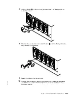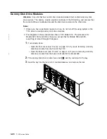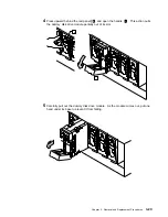
Fan-and-Power-Supply Assemblies
Attention: If you are servicing the 7133 under concurrent maintenance (see “Concurrent
Maintenance” on page 3-1), ensure that you have only one fan-and-power-supply
assembly removed from the 7133 at any time.
Notes:
1. Unless you have a particular reason to do so, do not turn off the using system or the
7133 when removing or installing fan-and-power-supply assemblies.
|
2. The diagrams in these instructions show a 7133 Model 010. The procedure for
|
Models 020, 500, and 600 is the same, except that for Models 500 and 600,
|
everything is turned through 90 degrees.
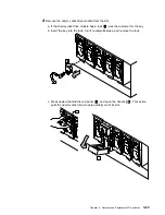
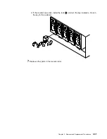
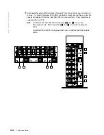
1
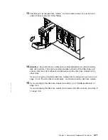
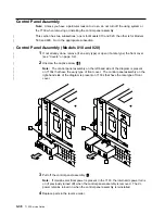
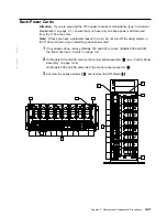
At the back of the 7133, unplug the power cable
1
from the fan-and-power-supply
assembly that you are going to remove.
|
Note: On
−
48 volt machines, each fan-and-power-supply has two power cables
|
whose plugs are held by latches. For each cable, press the latch, and pull out the
|
plug (see “Power (Model 020 with
−
48 V dc Fan-and-Power-Supply Assemblies)” on
|
page 3-10).
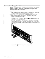
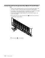
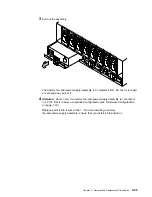
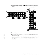
2
Open the latch
2
on the assembly you are going to remove.
3-32
7133 Service Guide
Содержание 7133 Series
Страница 1: ...7133 SSA Disk Subsystems Service Guide SY33 0185 02...
Страница 2: ......
Страница 3: ...7133 SSA Disk Subsystems Service Guide SY33 0185 02...
Страница 8: ...vi 7133 Service Guide...
Страница 14: ...xii 7133 Service Guide...
Страница 44: ...Labels Dummy Fan and Power Supply Assembly 1 30 7133 Service Guide...
Страница 94: ...2 10 7133 Service Guide...
Страница 110: ...2 2021 6 7133 Service Guide...
Страница 114: ...2 2022 4 7133 Service Guide...
Страница 138: ...2 2330 18 7133 Service Guide...
Страница 146: ...2 16 7133 Service Guide...
Страница 210: ...3 64 7133 Service Guide...
Страница 222: ...4 12 7133 Service Guide...
Страница 229: ......
Страница 230: ...Part Number 32H6990 Printed in the United Kingdom 32H699 SY33 185 2...

