


connectors 1-16
mainline-power connector
−
48 V dc
1-22
220 V ac and 300 V dc
1-22
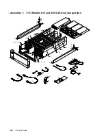
Models 010 and 020
back view
1-16
front view
1-23
Models 500 and 600
back view
1-19
front view
1-24
power control
1-25
remote-power-on control unit
1-25
control panel assembly
Models 010and 020
location 1-10
Models 500 and 600
location 1-11
removal and replacement
3-36
controls
power switch
Models 010 and 020
1-4
Models 500 and 600
1-6
remote-power-on control unit On/Off switch
1-25
D
Danger notices
power cables
3-9
power-supply unit
3-33
dc/ac voltage requirements
1-33
definition of FRU names used in SRN table
2-3
devices, finding the physical location
1-58
diagnostic aids
disk drive module POSTs (power-on self-tests)
2-1
installing SSA extensions to stand-alone
diagnostics 2-1
SRNs (service request numbers)
2-2
FRU names used in table
2-3
dimensions and weight
Models 010 and 020
1-31
Models 500 and 600
1-32
disk drive modules
acclimation 1-35
capacities 1-34
Check light
1-9
finding the physical location
1-58
how to recognize from a dummy module
1-29
identification 1-36
installing 3-22
Models 010 and 020
location 1-10
locks 1-10
Models 500 and 600
location 1-11
locks 1-11
numbering
Models 010 and 020
1-10
disk drive modules (continued)
numbering (continued)
Models 500 and 600
1-11
POSTs (power-on self-tests)
2-1
Power light
1-8
power sequencing
1-34
product-information label
1-29
Ready light
1-8
red panel
1-29
removing 3-17
removing a dummy
3-28
serial number and capacity label
1-29
dummy disk drive modules, how to recognize
1-29
dummy fan-and-power-supply assembly
removal and replacement
3-34
dummy-fan-and-power-supply assembly
label 1-30
E
electrical hazards
1-61
electrical requirements
1-33
empty-position warning label
Models 500 and 600
1-28
empty-position warning labels
Models 010 and 020
1-27
empty-slot warning label
Models 500 and 600
1-28
empty-slot warning labels
Models 010 and 020
1-27
environmental characteristics
Models 010 and 020
1-33
Models 500 and 600
1-34
explosive hazards
1-61
extensions (SSA) to stand-alone diagnostics,
installing 2-1
F
Fan-and-Power Check light
Models 010 and 020
1-4
Models 500 and 600
1-7
fan-and-power-supply assemblies
Fan-and-Power Check light
Models 010 and 020
1-4
Models 500 and 600
1-7
location
Models 010 and 020
1-10
Models 500 and 600
1-11
Power light
Models 010 and 020
1-4
Models 500 and 600
1-7
removal and replacement
3-32
fiber optic cables
1-14
fiber optic wrap adapter (Fibre-Optic Extenders)
1-14
X-2
7133 Service Guide
Содержание 7133 Series
Страница 1: ...7133 SSA Disk Subsystems Service Guide SY33 0185 02...
Страница 2: ......
Страница 3: ...7133 SSA Disk Subsystems Service Guide SY33 0185 02...
Страница 8: ...vi 7133 Service Guide...
Страница 14: ...xii 7133 Service Guide...
Страница 44: ...Labels Dummy Fan and Power Supply Assembly 1 30 7133 Service Guide...
Страница 94: ...2 10 7133 Service Guide...
Страница 110: ...2 2021 6 7133 Service Guide...
Страница 114: ...2 2022 4 7133 Service Guide...
Страница 138: ...2 2330 18 7133 Service Guide...
Страница 146: ...2 16 7133 Service Guide...
Страница 210: ...3 64 7133 Service Guide...
Страница 222: ...4 12 7133 Service Guide...
Страница 229: ......
Страница 230: ...Part Number 32H6990 Printed in the United Kingdom 32H699 SY33 185 2...


