


Chapter 5: Troubleshooting
84 Planning, Installation, and Maintenance Guide
This section describes how to resolve problems with the Network Station
when connected to the 5500 Control Unit. For detailed information, refer to
your Network Station user’s guide.
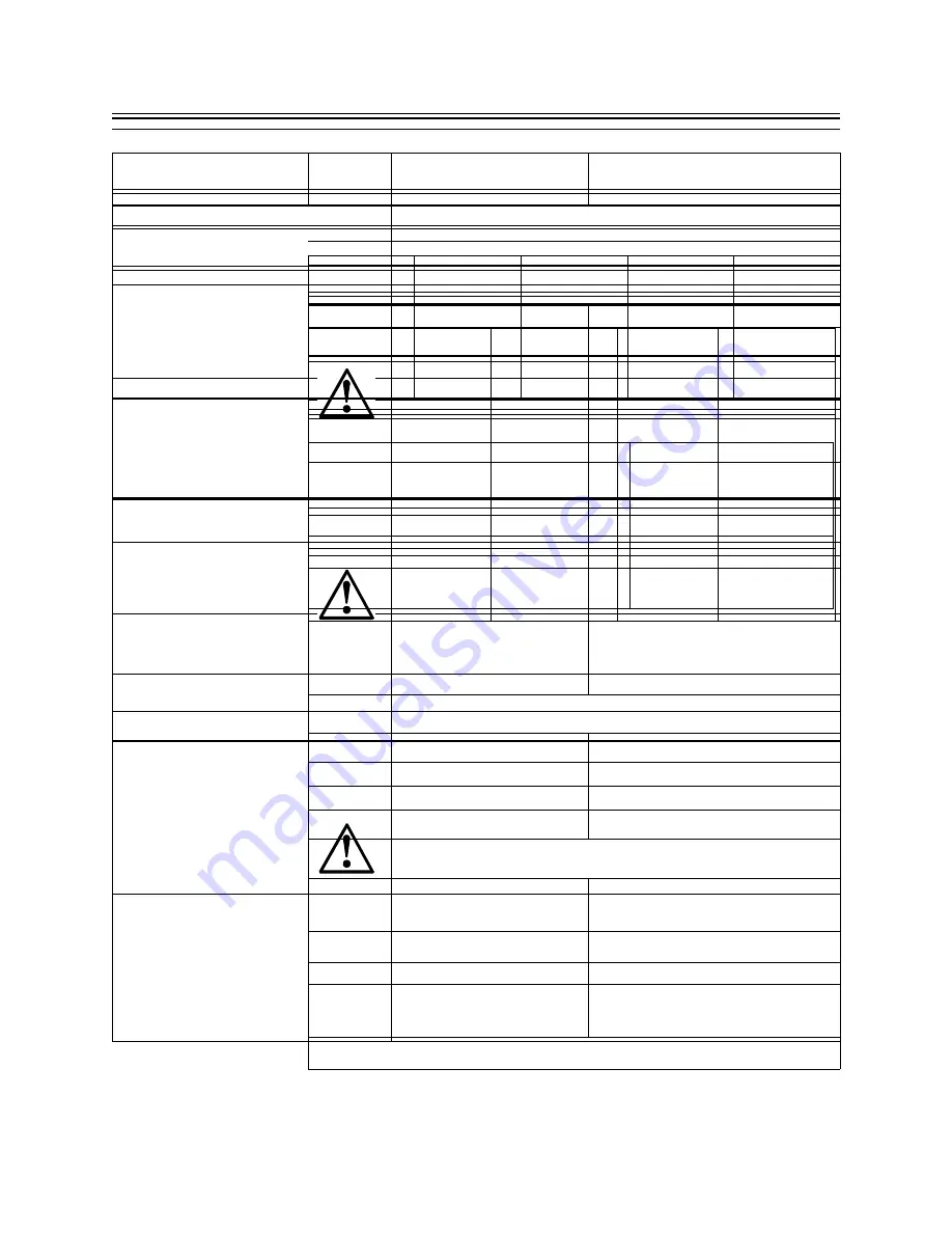
Figure 33: Network Station Troubleshooting
Symptom
What To Do
NS (Network Station) will not
connect to the 5500 Control Unit
1. Check power and network connections
2. Make sure IP addresses are correct for your host
configuration
3. Make sure IP addresses are correct for your booting host
4. Check for correct directory path for Boot Host. For the
IBM 5500 Control Unit, the path is /nstation/prodbase/
with TFTP protocol. For all other Boot Hosts, refer to the
Network Station documentation.
5. Check to make sure Kernel file is named under Network
Station Boot configuration
6. Check Twinax Network Stations for proper port addressing
NS boots, but results in a gray or light
background window
1. Check the IP address of the host configuration
2. Check for correct directory path for Boot Host. For the
IBM 5500 Control Unit, the path is /nstation/prodbase/
with TFTP protocol. For all other Boot hosts, refer to the
Network Station documentation.
3. Check to ensure standard.nsm is the configuration file on
the Network Station
Network Station cannot obtain a log
in screen or boots directly to menu
from 5500 Control Unit
1. Check the IP address for the host configuration
2. Ensure that file protocol is correctly set for the host
configuration
3. Create or edit the defaults.dft file on your NSM Host
configuration server as follows:
set exec-startup-commands =
{{“actlogin -authserve 9.163.226.101
a
”}}
Network Station boots but contains
wrong host login IP at Login window.
You must select ROAM to place
correct IP or Host name of
Configuration Host
Create or edit the defaults.dft file on your NSM Host
configuration server as follows:
set exec-startup-commands =
{{“actlogin -authserve 9.163.226.101
b
”}}
See “Using the 5500 Control Unit as a Network Station Boot
Server” on page 47.
85
Field Code Updates
Service and support personnel can obtain code updates through the following
web site:
Download the file to a diskette and use the 5500 Express IP Control Unit’s
diskette drive to update the driver and application code.
Network Station changes NVRAM
settings after properly booting to a
Configuration Host rather than the
5500 Control Unit
Create or edit the defaults.dft file on your configuration NSM
Host server as follows:
set config-auto-save-nvram = false
NS 3270 and 5250 cannot call telnet
host by name
Ensure that the Host name, Domain, and DNS entries are
correct in the 5500 Control Unit’s ConfigurationPlus program.
For information, see “Configuring the IBM 5500 Controller
ID” on page 61.
Network Station Navigator cannot
browse Intranet or Internet by name
of URL
1. Ensure Host Name, Domain, and DNS entries are correct
in the 5500 Control Unit’s ConfigurationPlus program.
2. Ensure that the SOCKS host and port number are correct in
the ConfigurationPlus program (see “Configuring SOCKS
Host for Network Station” on page 63).
Cannot delete the Network Station’s
Navigator bookmarks after the Boot
and Configuration files are
transferred from the 5500 Control
Unit
Go to the Main Menu, Utilities windows in the
ConfigurationPlus program. Select the option Delete
Bookmarks.
Network Station appears to have lost
connection.
1. Reboot the Network Station.
2. Check the cabling.
a. This number should be your IP or host name of the host configuration.
b. This number should be your IP or host name of the host configuration.
Figure 33: Network Station Troubleshooting
Symptom
What To Do
Chapter 5: Troubleshooting
86 Planning, Installation, and Maintenance Guide
FRU Part Numbers
The 5500 Control Unit is designed as a single field replaceable unit (FRU).
Configuration data might be recovered using the Utility diskette. The
following is a list of the field replaceable unit (FRU) part numbers:
When ordering a system FRU, separate diskettes should also be shipped along
with the FRU in order to bring the FRU up to the current level. Perform the
update on the FRU before trying to restore a saved configuration.
Contacting IBM Service
For IBM service, contact one of the following:
• Your IBM Representative
• Your IBM Authorized Business Partner
• IBM Direct at 1-800-IBM-CALL (1-800-426-2255, ask for department
AE001)
To identify your local IBM Authorized Business Partner or IBM
representative, call 1-800-IBM-4YOU (1-800-426-4968).
To obtain IBM Warranty Service, Maintenance Service, or IBM Hourly
Service, call 1-800-IBM-SERV (1-800-426-7378). IBM Hourly Service is
available at the applicable rate and terms, including the element exchange
price, if applicable.
Replacing Defective Units
To facilitate replacement of a defective 5500 Control Unit, keep a current
copy of the recovery file you created on the Utility Diskette using the
ConfigurationPlus program. (Refer to “Creating A Recovery File” on page
64.)
Description
Model 01E
Model 02E
Model 01T
Model 02T
System FRU
05J4937
05J4938
05J4939
05J4940
Twinax
Break-out
Box
21F5093
21F5093
21F5093
21F5093
87
Chapter 6: Twinax Client Cabling Requirements and
Problem Solving
This section describes the 5500 Control Unit’s twinax cabling requirements,
common problems and diagnostic tests. This section contains a step-by-step
procedure to resolve cabling problems and can be used for diagnosis with
three different cabling methods: twinax communication over standard twinax,
twinax over UTP, and twinax over IBM Cabling System.
DANGER
To avoid a shock hazard, do not connect or disconnect any cables or
perform installation, maintenance, or reconfiguration of this product during
an electrical storm.
DANGER
To avoid a shock hazard:
The power cord must be connected to a properly wired and earthed
receptacle.
Any equipment to which this product will be attached must also be con-
nected to properly wired receptacles.
DANGER
When possible, use one hand to connect or disconnect signal cables to
prevent a possible shock from touching two surfaces with different
electrical potentials.
Chapter 6: Twinax Client Cabling Requirements and Problem Solving
88 Planning, Installation, and Maintenance Guide
Guide to This Section
The following guide allows you to determine where in this section you should
begin your troubleshooting activity. Begin with the following section
“Common Cabling Concerns”. If this section does not help you solve your
problem, continue to the section on “Twinax Cabling Schemes” on page 89
Common Cabling Concerns
IBM recommends that you start here to help you understand cabling concerns
for the various cabling schemes that are used.
Figure 34: Common Cabling Concerns
Dual mode function and Express
considerations
See “Dual Mode Function
and Express
Considerations” on page
90
Common cable problems and associated
tests
See “Common Cable
Problems and Associated
Tests” on page 91
89
Twinax Cabling Schemes
Use this section to understand and troubleshoot the different twinax cabling
schemes. Identify the cabling scheme you are using in Figure 35 and follow
the debug sequence as shown.
Figure 35: Twinax Cabling Schemes
Twinax Cabling
Twinax cable standards
See “Twinax Cable Standards” on
page 96
Using Port Tester
See “Using the Port Tester” on
page 97
Troubleshooting twinax cable
problems
See “Troubleshooting Twinax
Cable Problems” on page 100
Advanced troubleshooting
See “Advanced Troubleshooting”
on page 103
Step-by-step cable debugging
See“Step-by-Step Cable
Debugging” on page 105
Checking cables using a current probe
See “Steps to Check Cable Using
a Current Probe” on page 109
Advance TDR procedure
See “Advanced Time Domain
Relfectometry (TDR) Procedure”
on page 113
IBM Cabling System
IBM Cabling System tests
See “IBM Cabling System Tests”
on page 124
Step-by-step cable debugging
See “Step-by-Step Cable
Debugging” on page 105
UTP Cabling
UTP cabling standards
See “UTP Cabling Standards” on
page 134
Using Port Tester
See “Using the Port Tester” on
page 97
Resolving UTP cabling problems
See “Resolving UTP Cabling
Problems” on page 138
Sources for Related Cable Information
Chapter 6: Twinax Client Cabling Requirements and Problem Solving
90 Planning, Installation, and Maintenance Guide
Dual Mode Function and Express Considerations
The following section describes Dual Mode and Express considerations.
Dual Mode and Multiplexers
Using twinax multiplexers can prevent you from using the full performance
capabilities of the 5500 Control Unit. Multiplexers combine the signals of
multiple ports into a single cable for a long transmission run. The signals are
then demultiplexed back into the separate ports. Because the legacy twinax
workstation controllers gave each port a separate time slice, a multiplexer’s
job was relatively easy. True time domain multiplexing was not necessary
because there was never more than one port active at a time.
You cannot use the old form of eight-port multiplexing (without true time
domain multiplexing) with new workstation controllers (WSC) driving two
ports at the same time (like that in the 5500 Control Unit). The signals from
the two ports would get garbled together, making twinax communication
impossible.
In order to be compatible with these old multiplexers, the Dual Mode
operation of the 5500 Control Unit can be set to disabled. If you do not want
to lose the performance gain associated with this function you can use two
multiplexers instead of one. Multiplex ports 0 through 3 together on one
multiplexer and ports 4 through 7 on the other. The best way is to upgrade the
multiplexer to one that supports the Dual Mode function such as the IBM
7299.
Optimized Mode
Optimized mode streamlines data transmissions to a target device so that
transmission occurs almost twice as fast as in normal transfers. This mode can
be used by enabled devices even though other devices on the same twinax
port do not support the 5250 Express Data Stream. This mode is also
independent of the cabling system being used; it runs on existing cables
without adding new restrictions.
2 Mbps Mode
For 2 Mbps mode to be used, all the devices operating on a given WSC port
must support the 5250 Express Data Stream. When 2 Mbps mode is used,
devices that do not support the 5250 Express Data Stream can be physically
cabled to the port, but they must be turned off or not operating. If any device
that does not support 2 Mbps mode suddenly becomes operational on the port,
Cable information
See “Sources for Related Cable
Information” on page 142
Figure 35: Twinax Cabling Schemes
91
all the devices on the port return to the standard 1 Mbps mode communication
rate.
For optimal performance, IBM recommends keeping your Express-enabled
devices on a separate port from your non-Express devices.
When planning for 2 Mbps mode, it is important to note that the maximum
support cable lengths are shorter than used with the standard twinax protocol.
For more information, see Figure 7 on page 33. If installed cables are too long
to support 2 Mbps mode, the WSC will operate at the standard 1 Mbps mode
rate.
Note: Not all UTP hubs or multiplexers support the Express data stream. The
IBM 7299 product family does support all functions of the Express data
stream and the Dual Mode function of the workstation controller.
Common Cable Problems and Associated Tests
This section describes some of the most common cable problems and the
common cable tests to isolate these problems. References to twinax cabling in
this section can refer to all three twinax cabling methods described in this
manual. Some common cable problems are:
• Power and grounding
• Wire resistance and attenuation
• Extraneous voltage on the signal wires
• Stubs, bridge taps, and extensions
• Wire characteristic impedance and impedance discontinuities
• Crosstalk
• Shorts, opens, and other wire faults
• Electromagnetic interference
Power Receptacle
Incorrectly wired or grounded power receptacles can be a safety hazard and
can contribute unacceptable levels of noise onto the network. In some cases,
the errors caused by incorrectly wired or grounded power receptacles are very
intermittent. If the AC voltage is not within acceptable limits, the attached
device can introduce errors onto the network or can fail to work.
Power Monitors
An OEM Power Disturbance Analyzer can be used to measure voltage sag,
surge, and impulse (including impulse duration) on single and three phase AC
supplies. With the appropriate plug-in module, it will also record DC voltages.
The output is numeric on a paper tape roll.
Chapter 6: Twinax Client Cabling Requirements and Problem Solving
92 Planning, Installation, and Maintenance Guide
Another OEM power monitor provides 8-channel digital storage of external
voltage waveforms. The recorded waveforms may be displayed on a screen.
The recording is triggered when a disturbance occurs that exceeds a
predefined limit.
Wire Resistance
Wire resistance measurements indicate the presence of opens, shorts, faults,
high-resistance connections, or incorrect wire sizes. Opens, shorts, or faults
usually cause an inoperative network. High-resistance connections or
incorrect wire sizes can cause:
• High error rates
• An inoperative network or attached device
Small wire size can limit the drive capability below the allowable distance
specified.
Measured Wire Resistance Length versus Electrical Length
Comparing the wire length determined by a resistance measurement to the
length measured by a time domain reflectometer can determine whether
different sizes of wire exist in the loop (that is, whether the wiring in the
building is consistent). See “Advanced Time Domain Relfectometry (TDR)
Procedure” on page 113. Do not use loops that contain different sizes of wire
for 5250 protocol transmission.
Wire length that exceeds the specified limits can cause:
• Excessive errors or intermittent errors
• An inoperative network or attached device
Characteristic Impedance
Wire whose characteristic impedance exceeds the specified limits might not
be suitable for high-speed data transmission. Increased error rates can result
from the use of such wire.
Impedance Discontinuities
Impedance discontinuities can be caused by any of the following that exist
along the wire path:
Opens
Shorts
Loose connections
Wiring stubs
Bridge taps
Loading circuits
Telephone jacks
Connector blocks
Excessive impedance discontinuities can cause:
Reflections that can increase the error rate
93
Erratic performance
In extreme cases, an inoperative network or attached device
Attenuation
Excessive attenuation (signal loss) can be caused by:
• The attenuation characteristics of the cable
• Wire that is too small
• Impedance discontinuities
Excessive attenuation will limit the drive capability below the specified
allowable distances.
Crosstalk
Excessive near-end crosstalk is a function of the design and manufacture of
the cable. Excessive crosstalk can cause:
• High error rates
• An inoperative network or attached device
• In extreme cases, false readings from the diagnostic procedures
DC Cable Tests
To check the DC continuity of a cable run, power the devices off. Unplug the
power cords of all devices on that cable run and remove the twinax cable from
the 5500 Control Unit twinax connector. As most meters use a voltage to
measure resistance, you will get incorrect results if there is any voltage
present on the cable that you are testing.
AC or DC Voltage on Signal Wires
The following voltages (depending on the magnitude) can be a safety hazard,
introduce errors into the network, or cause the network to be inoperative:
• AC voltage induced into the signal wires from nearby power or signal
cables
• AC or DC voltage caused by shorts or unintentional connection to other
circuits.
Minimum Cable Distances from Induced Noise Sources
With the5500 Control Unit, any induced voltages in the twinax cable shields
are collected at the twinax connector box, and passed up the cable to the card
connector. From the card connector, these voltages dissipate through the card
bracket to the unit’s chassis ground. If these voltages exceed certain levels,
problems can occur for other cards in the 5500 Control Unit. In these
conditions, the reason for the induced voltages must be located and resolved.
Chapter 6: Twinax Client Cabling Requirements and Problem Solving
94 Planning, Installation, and Maintenance Guide
Minimum distance of 15 feet if a twinax cable is installed near equipment or
power lines using 440 volts or more (especially if the equipment is carrying
hundreds of KVA).
Minimum distance between twinax cables and fluorescent, neon, or
incandescent lighting fixtures is 5 inches.
The minimum distance between twinax cabling and equipment or power lines
using less than 440 volts is as follows, depending on the power consumption:
Twinax Cabling Noise
If twinax cables are connected to the 5500 Control Unit, but are not connected
at the device end, or if the shield is open in a cable, this open cable or shield
can conduct noise into the system and cause 5500 Control Unit system
problems. Make sure that all attached twinax cables are properly terminated
and disconnect all unused twinax cables at the 5500 Control Unit’s twinax
brick.
AC Noise
AC Noise on twinax systems is either steady state noise or intermittent
transient noise.
When checking for AC noise, consider the possibility that the line is more
sensitive because of the number of cable connections or a cable length
approaching the maximum of 5000 feet (1524 meters). These distances are
shorter when running in Express mode or cabling is an unshielded twisted
pair.
Steady State AC Noise
This type of noise is measured between a known good ground (system ground
can be used if this has been checked for proper grounding) and twinax shield
with an AC voltmeter or an oscilloscope, after the twinax cabling is
disconnected from the system or controller. A voltage present indicates a
Figure 36: Twinax Cable Distances
Cable Description
2 KVA or less
2-5 KVA
over 5 KVA
Twinax and unshielded
power lines
5 inches
12 inches
24 inches
Twinax in grounded
metal conduit and
unshielded power lines
(or in ungrounded
metal conduit and
shielded power lines)
2.5 inches
6 inches
12 inches
Twinaxial and power
lines both in separate
grounded metal conduit
1.2 inches
3 inches
6 inches
Содержание 5500-01E
Страница 1: ...S05J 4934 00 5500 Express IP Control Unit Planning Installation and Maintenance Guide...
Страница 2: ......
Страница 3: ...S05J 4934 00 5500 Express IP Control Unit Planning Installation and Maintenance Guide...
Страница 16: ...xvi Planning Installation and Maintenance Guide...
Страница 30: ...Chapter 1 Introducing the IBM 5500 Express IP Control Unit 30 Planning Installation and Maintenance Guide...
Страница 48: ...Chapter 2 Planning Your Installation 48 Planning Installation and Maintenance Guide...
Страница 54: ...Chapter 3 Installing the 5500 Express IP Control Unit 54 Planning Installation and Maintenance Guide...
Страница 68: ...Chapter 4 Configuring the 5500 Express IP Control Unit 68 Planning Installation and Maintenance Guide...
Страница 144: ...144 Planning Installation and Maintenance Guide...
Страница 145: ...Appendix A 145...
Страница 146: ...146 Planning Installation and Maintenance Guide...
Страница 147: ...Appendix A 147...
Страница 148: ...148 Planning Installation and Maintenance Guide...
Страница 149: ...Appendix A 149...
Страница 150: ...150 Planning Installation and Maintenance Guide...
Страница 151: ...Appendix A 151...
Страница 152: ...152 Planning Installation and Maintenance Guide...
Страница 153: ...Appendix A 153...
Страница 154: ...154 Planning Installation and Maintenance Guide...
Страница 155: ...Appendix A 155...
Страница 156: ...156 Planning Installation and Maintenance Guide...
Страница 157: ...Appendix A 157...
Страница 158: ...158 Planning Installation and Maintenance Guide...
Страница 164: ...164 Planning Installation and Maintenance...
Страница 184: ...Glossary 184...
Страница 188: ...Index 4...
Страница 191: ......


