


book,
and
lift
place
assembly
tool,
PN
11P4369.
v
All
components
must
be
removed
from
the
system
unit
backplane
to
reduce
its
weight
to
a
minimum.
–
DCA
books
and
DCA
blanks
–
Capacitor
books
–
Network
interface
controller
(NIC)
card
–
Memory
books
and
memory
blanks
–
Processor
MSA
(air
mover)
assembly
–
MCM
modules
(processor)
and
pass-through
modules
(remove
the
MCMs
only
if
the
chassis
is
to
be
replaced)
–
L3
modules
(remove
the
L3
modules
only
if
the
chassis
is
to
be
replaced)
–
System
clock
card
v
The
lift
tool
wheels
must
be
chocked
to
prevent
it
from
moving
during
the
operation.
The
frame
must
not
be
on
its
casters,
the
leveling
pads
must
be
engaged
to
prevent
the
frame
from
moving
during
the
operation.
1.
Unpack
the
lift
tool
and
follow
assembly
instructions
included
with
the
tool.
Also,
refer
to
the
book.
Inspect
the
tool
for
damage
(do
not
perform
the
remove
procedure
with
a
damaged
lift
tool).
Read
all
safety
instructions
before
performing
this
operation.
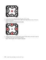
Replace
the
blue
lift
plate
with
the
orange
lift
plate.
(PN
11P4369).
Orient
two
round
holes
in
lift
plate
to
the
side
of
the
lift
tool
that
will
be
closest
to
the
frame.
2.
Power
off
the
system.
See
3.
Open
the
rack
doors
and
remove
them
from
the
rack.
4.
Verify
that
all
cables
are
labeled.
If
not,
then
label
all
cables
and
components
along
with
their
location
at
the
front
and
rear
of
the
system.
5.
Unplug
all
power
cables
from
the
line
power
source.
Attention:
Because
this
procedure
is
performed
with
power
removed
from
the
system,
references
to
using
the
white
or
green
service
buttons
on
the
UEPO
switch
do
not
apply
during
the
remainder
of
this
procedure.
6.
Unplug
any
cables
attached
to
the
Network
interface
controller
(NIC)
card
and
DCAs.
7.
At
the
back
of
the
system,
remove
the
safety
bars
from
the
Network
interface
controller
(NIC)
card,
using
an
allen
wrench
on
the
captive
screws.
8.
Remove
the
Network
interface
controller
(NIC)
card
or
cards.
See
9.
Remove
the
DCAs
and
capacitor
books
(and
blanks
if
applicable).
See
and
10.
At
the
front
of
the
system,
remove
the
safety
bars
from
the
memory
books
and
blanks.
11.
Remove
the
memory
books
(and
blanks
if
applicable).
See
12.
Remove
all
the
MSA
assemblies.
See
13.
Remove
the
MSA
enclosure.
See
14.
Remove
the
MCM
modules.
See
15.
Remove
the
L3
modules.
See
16.
Remove
the
clock
card.
See
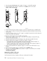
17.
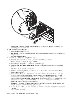
Remove
two
frame
extender
mounting
bolts
from
EIA
position
17
(10mm
bolt).
132
Hardware
(Remove
and
Replace;
Part
Locations
and
Listings)
Содержание 270
Страница 2: ......
Страница 12: ...x Hardware Remove and Replace Part Locations and Listings...
Страница 279: ...Figure 3 CCIN 2881 with pluggable DIMM Analyze hardware problems 267...
Страница 281: ...Figure 6 Models 830 SB2 with FC 9074 HSL and SPCN locations Analyze hardware problems 269...
Страница 283: ...Figure 1b Model 840 SB3 processor tower dual line cord Analyze hardware problems 271...
Страница 294: ...01 gif port and LED locations 282 Hardware Remove and Replace Part Locations and Listings...
Страница 295: ...s src rzaq4519 gif locations Analyze hardware problems 283...
Страница 318: ...Figure 2 FC 5088 FC 0588 Expansion I O Unit top view 306 Hardware Remove and Replace Part Locations and Listings...
Страница 415: ...Table 2 Final assembly rear Models 830 and SB2 with FC 9074 continued Analyze hardware problems 403...
Страница 422: ...Table 1 Cover assembly Models 840 and SB3 processor tower 410 Hardware Remove and Replace Part Locations and Listings...
Страница 483: ...Table 1 Cover assembly FC 5095 Expansion I O Tower Analyze hardware problems 471...
Страница 505: ...Table 15 Model 830 SB2 System Unit with FC 9074 Power cables single line cord Analyze hardware problems 493...
Страница 511: ...Table 19 Model 840 SB3 Processor Tower Power cables single line cord Analyze hardware problems 499...
Страница 513: ...Table 21 Model 840 and Model SB3 9079 Base I O Tower Power cables dual line cord Analyze hardware problems 501...
Страница 519: ...Figure 15 Models 870 and 890 Primary I O to CEC interconnection part 1 Analyze hardware problems 507...
Страница 614: ...602 Hardware Remove and Replace Part Locations and Listings...
Страница 618: ...606 Hardware Remove and Replace Part Locations and Listings...
Страница 621: ......
Страница 622: ...Printed in USA SY44 5917 02...