


5.
Install
an
L3
module.
6.
Press
the
Rocker
switch
forward
to
the
MCM/L3
Pwr/GND
position.
This
checks
the
L3s
for
power
to
ground
shorts.
It
also
checks
the
MCM
for
power
to
ground
shorts.
Note
the
following:
v
The
green
L3
LED
must
be
lit
for
a
pass
condition.
If
the
amber
L3
is
lit,
there
may
be
a
short
between
one
of
the
two
L3
voltages
and
GND,
which
is
a
fail
state,
or
the
combination
of
memory
books,
I/O
books,
and
L3
in
parallel
are
creating
a
low
resistance.
Perform
the
following:
a.
Disengage
memory
books
followed
by
I/O
books
one
at
a
time.
b.
Repeat
this
test
after
each
is
removed
until
either
the
L3
test
passes,
or
all
memory
and
I/O
are
disengaged
and
the
L3
test
remains
in
a
fail
state.
c.
If
after
disengaging
all
memory
and
I/Os,
the
L3
LED
remains
lit,
remove
the
L3
and
inspect
the
interposer
for
shorts.
d.
Reinstall
the
L3
once
and
repeat
the
test.
If
the
fail
persists,
replace
the
L3.
v
The
green
MCM
LED
must
be
lit
for
a
pass
condition.
If
the
amber
MCM
Led
is
lit,
there
is
a
short
across
the
MCM
voltage
and
GND.
Perform
the
MCM/passthru
test
and
correct
the
short
condition
before
powering
on.
7.
Press
the
Rocker
switch
backward
to
the
L3
PWR/PWR
position.
Both
the
green
and
amber
MCM
LED
will
be
off.
Power
is
removed
from
these
circuits
when
the
switch
is
in
this
position.
Note
the
following:
The
green
L3
LED
must
be
lit
for
a
pass
condition.
If
the
amber
L3
LED
is
lit,
there
is
a
short
between
the
two
L3
power
domains.
Perform
the
following:
a.
Remove
the
L3
and
inspect
the
interposer
for
shorts.
b.
Reinstall
the
L3
once
and
repeat
the
test.
If
the
fail
persists,
replace
the
L3.
8.
Repeat
steps
5
(See
page
6
(See
page
and
7
(See
page
until
all
required
L3s
are
installed.
This
ends
the
procedure.
Test
method
2
:
Testing
MCM
and
passthru
modules
for
a
short
circuit
using
a
multimeter
and
capacitor
book:
There
are
two
procedures
that
are
covered
in
this
topic:
v
Testing
MCM
and
passthru
modules
for
a
short
circuit
(See
page
v
Testing
L3
cache
modules
for
a
short
circuit
(See
page
Test
method
2:
Testing
MCM
and
passthru
modules
for
a
short
circuit
Perform
this
test
to
ensure
that
a
short
circuit
was
not
created
when
installing
an
MCM
or
passthru
module.
You
can
use
one
of
the
following
two
options
during
the
MCM
replacement:
v
Install
and
use
a
multimeter
and
new
capacitor
book
(part
44P2471)
v
Install
and
use
a
multimeter,
the
original
capacitor
book,
and
MCM/L3
module
short-circuit
test
tool
(part
44P0209)
Note:
This
procedure
should
only
be
performed
by
trained
personnel.
Ensure
the
UEPO
switch
is
in
the
Off
position
before
performing
this
procedure.
MCM
installation
shorts
test,
procedure
1
1.
Power
down
the
system.
See
2.
Ensure
the
UEPO
is
off.
3.
Disengage
all
DCAs
from
the
planar.
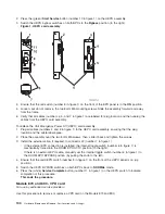
4.
Choose
from
the
following
options:
v
If
you
are
using
the
new
capacitor
book
option:
Install
the
Capacitor
book
in
CAP
base
location
(M33),
with
no
meter
attached.
126
Hardware
(Remove
and
Replace;
Part
Locations
and
Listings)
Содержание 270
Страница 2: ......
Страница 12: ...x Hardware Remove and Replace Part Locations and Listings...
Страница 279: ...Figure 3 CCIN 2881 with pluggable DIMM Analyze hardware problems 267...
Страница 281: ...Figure 6 Models 830 SB2 with FC 9074 HSL and SPCN locations Analyze hardware problems 269...
Страница 283: ...Figure 1b Model 840 SB3 processor tower dual line cord Analyze hardware problems 271...
Страница 294: ...01 gif port and LED locations 282 Hardware Remove and Replace Part Locations and Listings...
Страница 295: ...s src rzaq4519 gif locations Analyze hardware problems 283...
Страница 318: ...Figure 2 FC 5088 FC 0588 Expansion I O Unit top view 306 Hardware Remove and Replace Part Locations and Listings...
Страница 415: ...Table 2 Final assembly rear Models 830 and SB2 with FC 9074 continued Analyze hardware problems 403...
Страница 422: ...Table 1 Cover assembly Models 840 and SB3 processor tower 410 Hardware Remove and Replace Part Locations and Listings...
Страница 483: ...Table 1 Cover assembly FC 5095 Expansion I O Tower Analyze hardware problems 471...
Страница 505: ...Table 15 Model 830 SB2 System Unit with FC 9074 Power cables single line cord Analyze hardware problems 493...
Страница 511: ...Table 19 Model 840 SB3 Processor Tower Power cables single line cord Analyze hardware problems 499...
Страница 513: ...Table 21 Model 840 and Model SB3 9079 Base I O Tower Power cables dual line cord Analyze hardware problems 501...
Страница 519: ...Figure 15 Models 870 and 890 Primary I O to CEC interconnection part 1 Analyze hardware problems 507...
Страница 614: ...602 Hardware Remove and Replace Part Locations and Listings...
Страница 618: ...606 Hardware Remove and Replace Part Locations and Listings...
Страница 621: ......
Страница 622: ...Printed in USA SY44 5917 02...


