


g.
Continue
with
step
9
(See
page
to
set
the
configuration
ID.
8.
Perform
steps
23
(See
page
and
24
(See
page
in
the
Expansion
unit
power
procedure.
Then,
return
here
and
continue
with
the
next
step.
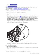
9.
Set
the
configuration
ID
in
the
tower
card:
a.
If
the
ac
power
is
not
applied,
then
apply
it
now.
Note:
The
tower
may
power
up
automatically.
b.
Power
down
the
expansion
tower
without
removing
the
power
cord
using
the
Then,
return
here
and
continue
with
the
next
step.
c.
Select
function
07
on
the
system
panel.
Press
Enter
.
(
07**
will
be
displayed)
d.
Use
the
arrow
keys
to
increment/decrement
to
sub-function
A9
(
07A9
will
be
displayed).
Press
Enter
(
07A9
00
will
be
displayed).
e.
Use
the
arrow
keys
to
increment/decrement
to
the
frame
address,
nn
(nn
is
usually
02,
03,
and
so
forth
for
expansion
towers)
(
07nn
will
be
displayed).
Press
Enter
(
07nn
00
will
be
displayed).
Note:
The
display
on
the
addressed
frame
should
now
be
blinking
on
and
off.
f.
Use
the
arrow
keys
to
increment/decrement
to
a
configuration
ID.
v
The
configuration
ID
is
8A
for
FC
5094.
v
The
configuration
ID
is
99
for
FC
9094.
(
078x
will
be
displayed).
Press
Enter
(
078x
00
will
be
displayed).
g.
After
a
few
seconds,
the
display
on
the
addressed
FC
5094,
FC
9094
frame
will
stop
blinking
and
return
to
displaying
the
frame
address.
On
a
FC
9094,
the
display
will
show
07xx
00
,
indicating
success.
Use
the
arrow
keys
to
increment/decrement
until
07**
is
shown.
Press
Enter
to
return
the
panel
to
07.
190
Hardware
(Remove
and
Replace;
Part
Locations
and
Listings)
Содержание 270
Страница 2: ......
Страница 12: ...x Hardware Remove and Replace Part Locations and Listings...
Страница 279: ...Figure 3 CCIN 2881 with pluggable DIMM Analyze hardware problems 267...
Страница 281: ...Figure 6 Models 830 SB2 with FC 9074 HSL and SPCN locations Analyze hardware problems 269...
Страница 283: ...Figure 1b Model 840 SB3 processor tower dual line cord Analyze hardware problems 271...
Страница 294: ...01 gif port and LED locations 282 Hardware Remove and Replace Part Locations and Listings...
Страница 295: ...s src rzaq4519 gif locations Analyze hardware problems 283...
Страница 318: ...Figure 2 FC 5088 FC 0588 Expansion I O Unit top view 306 Hardware Remove and Replace Part Locations and Listings...
Страница 415: ...Table 2 Final assembly rear Models 830 and SB2 with FC 9074 continued Analyze hardware problems 403...
Страница 422: ...Table 1 Cover assembly Models 840 and SB3 processor tower 410 Hardware Remove and Replace Part Locations and Listings...
Страница 483: ...Table 1 Cover assembly FC 5095 Expansion I O Tower Analyze hardware problems 471...
Страница 505: ...Table 15 Model 830 SB2 System Unit with FC 9074 Power cables single line cord Analyze hardware problems 493...
Страница 511: ...Table 19 Model 840 SB3 Processor Tower Power cables single line cord Analyze hardware problems 499...
Страница 513: ...Table 21 Model 840 and Model SB3 9079 Base I O Tower Power cables dual line cord Analyze hardware problems 501...
Страница 519: ...Figure 15 Models 870 and 890 Primary I O to CEC interconnection part 1 Analyze hardware problems 507...
Страница 614: ...602 Hardware Remove and Replace Part Locations and Listings...
Страница 618: ...606 Hardware Remove and Replace Part Locations and Listings...
Страница 621: ......
Страница 622: ...Printed in USA SY44 5917 02...


