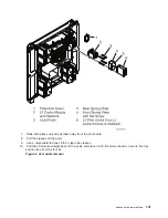
3.
Find
the
location
of
the
MDA
to
be
replaced
in
4.
Note
the
state
of
the
MDA’s
LED.
Then,
press
the
(green)
Start
Service
button
on
the
UEPO
panel.
5.
Proceed
only
if
the
MDA
LED
is
off,
or
the
repair
has
been
scheduled
(System
outage
-
EPO
off).
6.
Loosen
the
thumb
screws
on
the
MDA,
and
unplug
the
MDA
from
the
face
of
the
MSA.
Note:
The
MDA
weighs
approximately
0.45
Kg
(one
pound).
To
replace
the
MDA:
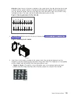
1.
Plug
the
MDA
onto
the
face
of
the
MSA,
aligning
the
two
metal
lips
on
the
face
of
the
MSA
with
the
slots
in
the
MDA.
Push
gently
to
seat
the
blind
mate
connector.
2.
Tighten
the
thumb
screws
on
the
MDA.
3.
Plug
all
cables
to
the
MDA,
ensuring
correspondence
of
plug
locations
and
cable
labeling.
4.
To
indicate
completion
of
these
steps,
press
the
(white)
Service
Complete
button
on
the
UEPO
panel.
This
ends
the
procedure.
Models
870
and
890
-
Memory
books
and
memory
blanks
For
use
by
authorized
service
providers.
Use
this
procedure
to
remove
or
replace
the
memory
books
and
memory
blanks
on
the
Models
870
and
890.
To
remove
or
replace
memory
books
and
memory
blanks:
1.
Power
off
the
system.
See
2.
Open
the
front
cover.
See
3.
Unscrew
the
thumb
screws
on
the
top
and
bottom
of
the
lock
bar,
in
front
of
the
memory
book
to
be
removed.
4.
Grasp
the
release
latches
located
at
the
top
and
bottom
of
the
memory
book
between
your
thumb
and
index
finger,
press
the
tabs
together.
Pivot
the
tabs
and
pull
the
book
straight
back.
5.
Reverse
this
procedure
to
install
the
memory
books
and
memory
blanks.
This
ends
the
procedure.
Models
870
and
890
-
Motor
scroll
assembly
(MSA)
air
filters
For
use
by
authorized
service
providers.
Use
this
procedure
to
remove
or
replace
the
Motor
scroll
assembly
(MSA)
air
filters
on
the
Models
870
and
890.
The
cage
air
filters
are
located
in
two
slots
on
the
front
of
the
CEC
cage,
beside
the
air
moving
devices
(AMDs),
one
above
the
other.
See
Figure
1.
in
for
details.
Attention:
The
filters
(P/N
11P3781)
must
be
inspected
every
six
months
and
replaced
as
necessary
to
maintain
proper
air
flow.
Filters
must
be
replaced
if
dirty
-
do
not
clean
filters.
It
is
not
necessary
to
remove
power
to
the
system
or
blower
assemblies
to
replace
the
air
filters.
To
remove
or
replace
the
MSA
air
filters:
1.
Do
not
power
down
the
system
if
it
is
powered
on.
This
procedure
can
be
performed
concurrently.
2.
Open
the
cover
to
access
the
FRU.
See
3.
Grasp
the
finger
tabs
on
the
filter
being
serviced,
and
pull
it
straight
out.
The
top
filter
is
for
MSA
X4
(location
H4),
the
bottom
filter
is
for
MSA
X3
(location
H3).
4.
To
replace
the
air
filters,
slide
the
air
filter
into
the
slot.
The
filter
is
keyed
to
ensure
correct
orientation.
This
ends
the
procedure.
112
Hardware
(Remove
and
Replace;
Part
Locations
and
Listings)
Содержание 270
Страница 2: ......
Страница 12: ...x Hardware Remove and Replace Part Locations and Listings...
Страница 279: ...Figure 3 CCIN 2881 with pluggable DIMM Analyze hardware problems 267...
Страница 281: ...Figure 6 Models 830 SB2 with FC 9074 HSL and SPCN locations Analyze hardware problems 269...
Страница 283: ...Figure 1b Model 840 SB3 processor tower dual line cord Analyze hardware problems 271...
Страница 294: ...01 gif port and LED locations 282 Hardware Remove and Replace Part Locations and Listings...
Страница 295: ...s src rzaq4519 gif locations Analyze hardware problems 283...
Страница 318: ...Figure 2 FC 5088 FC 0588 Expansion I O Unit top view 306 Hardware Remove and Replace Part Locations and Listings...
Страница 415: ...Table 2 Final assembly rear Models 830 and SB2 with FC 9074 continued Analyze hardware problems 403...
Страница 422: ...Table 1 Cover assembly Models 840 and SB3 processor tower 410 Hardware Remove and Replace Part Locations and Listings...
Страница 483: ...Table 1 Cover assembly FC 5095 Expansion I O Tower Analyze hardware problems 471...
Страница 505: ...Table 15 Model 830 SB2 System Unit with FC 9074 Power cables single line cord Analyze hardware problems 493...
Страница 511: ...Table 19 Model 840 SB3 Processor Tower Power cables single line cord Analyze hardware problems 499...
Страница 513: ...Table 21 Model 840 and Model SB3 9079 Base I O Tower Power cables dual line cord Analyze hardware problems 501...
Страница 519: ...Figure 15 Models 870 and 890 Primary I O to CEC interconnection part 1 Analyze hardware problems 507...
Страница 614: ...602 Hardware Remove and Replace Part Locations and Listings...
Страница 618: ...606 Hardware Remove and Replace Part Locations and Listings...
Страница 621: ......
Страница 622: ...Printed in USA SY44 5917 02...


