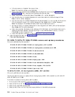
5.
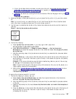
A
listing
of
the
power
domain
is
shown.
Select
the
Power
off
domain
function
key.
Everything
within
the
IOA’s
or
IOP’s
power
domain
will
be
powered
off
.
6.
To
see
the
status
of
the
power
domain,
select
the
Display
power
states
function
key.
7.
Find
the
IOA
or
IOP
that
you
are
removing
and
select
Toggle
LED
blink
off/on
.
8.
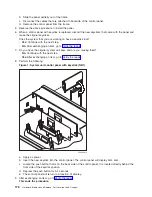
Open
the
rear
cover
to
access
the
card
that
you
are
removing
from
the
system.
See
9.
Remove
the
EMC
access
plate
that
is
located
directly
above
the
card
enclosure.
Remove
the
screw
from
the
top
of
the
access
plate
(cover)
and
tilt
the
top
of
the
cover
away
from
the
frame
to
remove
it.
10.
Look
at
the
power
LED
for
the
card
that
you
are
removing
to
ensure
that
it
is
powered
off.
The
power
LED
is
located
to
the
left
of
and
directly
above
the
card
slot.
If
the
LED
is
blinking
multiple
times
per
second
(rapidly)
or
it
is
off,
then
the
card
is
powered
off.
11.
Disconnect
and
label
any
cables
from
the
card
that
you
wish
to
remove.
12.
Turn
the
latch
counter
clockwise
and
lift
upward
on
the
other
latch
to
release
the
card.
13.
Gently
pull
the
card
off
the
backplane.
This
ends
the
procedure.
To
replace
cards
concurrently:
1.
Install
the
card
in
to
the
system
by
reversing
the
card
removal
procedure
above.
2.
Select
the
Power
on
domain
function
key
for
the
IOA
or
IOP
that
you
are
installing.
Note:
To
the
right
of
the
description
field
you
will
see
one
or
both
of
the
following
symbols
displayed.
Symbol
Indication
*
Indicates
the
location
to
which
the
system
will
assign
the
resource.
>
Indicates
the
location
to
which
the
resource
was
last
assigned.
3.
Press
Enter
.
The
Work
with
Controlling
Resource
display
will
appear.
4.
Determine
the
location
where
you
want
to
assign
the
resource
and
select
Assign
to
for
that
location.
5.
Wait
for
the
Hardware
Resource
Concurrent
Maintenance
display
to
appear
with
the
message
indicating
that
the
power
on
is
complete.
6.
After
exchanging
an
item,
go
to
Note:
If
you
have
exchanged
a
2766
or
2787
Fibre
Channel
IOA,
the
IBM
2105
disk
unit
subsystem
must
be
updated
to
use
the
World-Wide
Port-Name
of
the
new
2766
or
2787
IOA.
This
name
can
be
found
in
the
Port
worldwide
name
field
on
the
iSeries
server
by
displaying
detail
on
the
2766
or
2787
IOA
Logical
Hardware
Resource
information
in
Hardware
Service
Manager
in
SST/DST.
The
16-digit
World-Wide
Port-Name
can
also
be
determined
by
appending
the
digits
″
1000
″
to
the
beginning
of
the
12-digit
IEEE
Address
found
on
the
tailstock
label
of
the
Fibre
Channel
IOA.
Use
the
ESS
Web
Interface
User’s
Guide
(SC26-7346)
to
update
the
World-Wide
Port-Name
in
the
host
configuration
on
the
IBM
2105
ESS.
The
ESS
Web
Interface
User’s
Guide
can
also
be
found
at
the
following
URL:
http://ssddom02.storage.ibm.com/disk/ess/documentation.html
This
ends
the
procedure.
FC
8094-001
(lower
half),
FC
9094
-
Cards
(dedicated)
For
use
by
authorized
service
providers.
Use
this
procedure
to
remove
or
replace
cards
using
dedicated
maintenance
in
an
FC
8094-001
(lower
half),
FC
9094.
In
some
cases,
you
do
not
need
to
power
down
the
system
to
change
PCI
cards.
Use
the
guidelines
in
to
determine
if
you
should
use
dedicated
or
concurrent
remove
and
replace
procedures.
174
Hardware
(Remove
and
Replace;
Part
Locations
and
Listings)
Содержание 270
Страница 2: ......
Страница 12: ...x Hardware Remove and Replace Part Locations and Listings...
Страница 279: ...Figure 3 CCIN 2881 with pluggable DIMM Analyze hardware problems 267...
Страница 281: ...Figure 6 Models 830 SB2 with FC 9074 HSL and SPCN locations Analyze hardware problems 269...
Страница 283: ...Figure 1b Model 840 SB3 processor tower dual line cord Analyze hardware problems 271...
Страница 294: ...01 gif port and LED locations 282 Hardware Remove and Replace Part Locations and Listings...
Страница 295: ...s src rzaq4519 gif locations Analyze hardware problems 283...
Страница 318: ...Figure 2 FC 5088 FC 0588 Expansion I O Unit top view 306 Hardware Remove and Replace Part Locations and Listings...
Страница 415: ...Table 2 Final assembly rear Models 830 and SB2 with FC 9074 continued Analyze hardware problems 403...
Страница 422: ...Table 1 Cover assembly Models 840 and SB3 processor tower 410 Hardware Remove and Replace Part Locations and Listings...
Страница 483: ...Table 1 Cover assembly FC 5095 Expansion I O Tower Analyze hardware problems 471...
Страница 505: ...Table 15 Model 830 SB2 System Unit with FC 9074 Power cables single line cord Analyze hardware problems 493...
Страница 511: ...Table 19 Model 840 SB3 Processor Tower Power cables single line cord Analyze hardware problems 499...
Страница 513: ...Table 21 Model 840 and Model SB3 9079 Base I O Tower Power cables dual line cord Analyze hardware problems 501...
Страница 519: ...Figure 15 Models 870 and 890 Primary I O to CEC interconnection part 1 Analyze hardware problems 507...
Страница 614: ...602 Hardware Remove and Replace Part Locations and Listings...
Страница 618: ...606 Hardware Remove and Replace Part Locations and Listings...
Страница 621: ......
Страница 622: ...Printed in USA SY44 5917 02...


