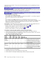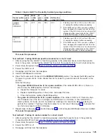
Table
2.
Check
LGA-ST
for
the
ability
to
detect
passing
conditions
Rocker
switch
position
MCM
green
LED
MCM
amber
LED
L3
green
LED
L3
amber
LED
Battery
low
amber
LED
Note
Forward
MCM/L3
PWR/GND
ON
OFF
ON
OFF
OFF
1.
If
Battery
Low
LED
is
ON,
or
if
no
LEDs
are
lit,
replace
the
battery
before
proceeding.
2.
If
the
MCM
and
L3
LEDs
are
not
as
defined
here,
disengage
the
capacitor
book
from
the
system.
If
the
LED
state
is
not
as
shown
after
disengaging
the
capacitor
book,
the
LGA-ST
is
defective.
Replace
it
before
proceeding.
Backward
L3
PWR/PWR
OFF
OFF
ON
OFF
OFF
1.
If
Battery
Low
LED
is
ON,
or
if
no
LEDs
are
lit,
replace
the
battery
before
proceeding.
2.
If
the
MCM
and
L3
LEDs
are
not
as
defined
here,
disengage
the
capacitor
book
from
the
system.
If
the
LED
state
is
not
as
shown
after
disengaging
the
capacitor
book,
the
LGA-ST
is
defective.
Replace
it
before
proceeding.
This
ends
this
procedure.
Test
method
1:
Testing
MCM
and
passthru
modules
for
a
short
circuit
1.
After
ensuring
that
the
LGA-ST
is
functioning
properly
in
the
procedure
above,
install
the
capacitor
book
in
the
system,
connecting
the
LGA-ST
test
box
onto
the
capacitor
book
9
pin
D-shell
connector.
2.
Power
down
the
system.
See
3.
Ensure
the
UEPO
is
off.
4.
Disengage
all
DCAs
from
the
backplane.
5.
Install
an
MCM/passthru
module.
6.
Press
the
Rocker
switch
forward
to
the
MCM/L3
PWR/GND
position.
This
checks
the
MCM
passthru
for
power
to
ground
shorts.
It
also
checks
the
L3s
for
power
to
ground
shorts
with
the
switch
in
this
position.
Note
the
following:
v
The
green
MCM
LED
must
be
lit
for
a
pass
condition.
If
the
amber
MCM
LED
is
lit,
there
is
a
short
across
the
MCM/passthru.
Perform
the
following:
a.
Inspect
the
interposer
for
shorts.
b.
Replace
the
MCM/passthru
in
the
system,
and
repeat
this
step.
c.
If
the
short
remains,
replace
the
MCM/passthru.
v
The
green
L3
LED
must
be
lit
for
a
pass
condition.
If
the
amber
L3
LED
is
lit,
there
may
be
a
short
between
one
of
the
two
L3
voltages
and
GND
which
is
a
fail
state,
or
the
combination
of
memory
books,
I/O
books,
and
L3
in
parallel
are
creating
a
low
resistance.
Before
powering
on,
perform
Test
method
1:
Testing
L3
cache
modules
for
a
short
circuit
(See
page
to
ensure
that
no
shorts
are
present
on
the
L3
modules.
7.
Repeat
steps
5
(See
page
and
6
(See
page
until
all
required
MCMs/passthrus
are
installed.
This
ends
this
procedure.
Test
method
1:
Testing
L3
cache
modules
for
a
short
circuit
1.
After
ensuring
that
the
LGA-ST
is
functioning
properly,
install
the
Capacitor
book
in
the
system
by
connecting
LGA-ST
test
head
onto
the
Capacitor
book
9
pin
D-Shell
connector.
2.
Power
down
the
system.
See
3.
Ensure
the
UEPO
is
off.
4.
Disengage
all
DCAs
from
the
backplane.
Analyze
hardware
problems
125
Содержание 270
Страница 2: ......
Страница 12: ...x Hardware Remove and Replace Part Locations and Listings...
Страница 279: ...Figure 3 CCIN 2881 with pluggable DIMM Analyze hardware problems 267...
Страница 281: ...Figure 6 Models 830 SB2 with FC 9074 HSL and SPCN locations Analyze hardware problems 269...
Страница 283: ...Figure 1b Model 840 SB3 processor tower dual line cord Analyze hardware problems 271...
Страница 294: ...01 gif port and LED locations 282 Hardware Remove and Replace Part Locations and Listings...
Страница 295: ...s src rzaq4519 gif locations Analyze hardware problems 283...
Страница 318: ...Figure 2 FC 5088 FC 0588 Expansion I O Unit top view 306 Hardware Remove and Replace Part Locations and Listings...
Страница 415: ...Table 2 Final assembly rear Models 830 and SB2 with FC 9074 continued Analyze hardware problems 403...
Страница 422: ...Table 1 Cover assembly Models 840 and SB3 processor tower 410 Hardware Remove and Replace Part Locations and Listings...
Страница 483: ...Table 1 Cover assembly FC 5095 Expansion I O Tower Analyze hardware problems 471...
Страница 505: ...Table 15 Model 830 SB2 System Unit with FC 9074 Power cables single line cord Analyze hardware problems 493...
Страница 511: ...Table 19 Model 840 SB3 Processor Tower Power cables single line cord Analyze hardware problems 499...
Страница 513: ...Table 21 Model 840 and Model SB3 9079 Base I O Tower Power cables dual line cord Analyze hardware problems 501...
Страница 519: ...Figure 15 Models 870 and 890 Primary I O to CEC interconnection part 1 Analyze hardware problems 507...
Страница 614: ...602 Hardware Remove and Replace Part Locations and Listings...
Страница 618: ...606 Hardware Remove and Replace Part Locations and Listings...
Страница 621: ......
Страница 622: ...Printed in USA SY44 5917 02...


