


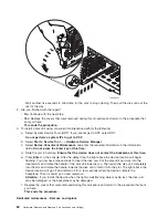


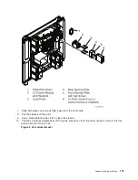


c.
Pull
the
PCI
card
enclosure
partially
out
of
the
frame
to
the
release
mechanism
stop
on
the
right
side,
while
lifting
the
cables
clear
of
the
enclosure.
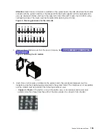
d.
Remove
the
PCI
cards
on
the
right
side
of
the
enclosure
preventing
access
to
the
battery
from
the
enclosure
and
note
their
locations.
See
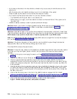
5.
Remove
the
TOD
battery.
Use
a
flat
object
(screwdriver)
to
pry
the
battery
out.
6.
Reverse
the
steps
to
install
the
TOD
battery.
7.
After
installation
is
complete,
IPL
the
system
in
Manual
Mode.
8.
Have
the
customer
set
the
time
and
date.
This
ends
the
procedure.
Models
870
and
890
remove
and
replace
procedures
For
use
by
authorized
service
providers.
Models
870
and
890
(FC
9094
with
single
line
cord)
-
AC
module
-
A01
and
A02
Models
870
and
890
(FC
9094
with
dual
line
cord)
-
AC
module
-
A01
and
A02
Models
870
and
890
(FC
9094)
-
Air
moving
device
-
B01
and
B02
Models
870
and
890
-
Bulk
power
controller
(BPC)
Models
870
and
890
-
Bulk
power
distribution
(BPD)
Models
870
and
890
-
Bulk
power
enclosure
(BPE)
Models
870
and
890
-
Bulk
power
f-airmover
(BPF)
Models
870
and
890
-
Bulk
power
regulator
(BPR)
Models
870
and
890
-
Capacitor
books
and
blanks
Models
870
and
890
(FC
9094)
-
Cards
(concurrent)
Models
870
and
890
(FC
9094)
-
Cards
(dedicated)
Models
870
and
890
(FC
9094)
-
Control
panel
-
NB1
Models
870
and
890
-
Covers
Models
870
and
890
-
DC
converter
assembly
(DCA)
Models
870
and
890
(FC
9094)
-
Device
board
-
DB1
and
DB2
Models
870
and
890
(FC
9094)
-
Device
board
-
DB3
Models
870
and
890
(FC
9094)
-
Disk
unit
(concurrent)
Models
870
and
890
(FC
9094)
-
Disk
unit
(dedicated)
Models
870
and
890
-
L3
modules
Models
870
and
890
-
MCM
module
(processor)
and
pass-through
modules
92
Hardware
(Remove
and
Replace;
Part
Locations
and
Listings)
Содержание 270
Страница 2: ......
Страница 12: ...x Hardware Remove and Replace Part Locations and Listings...
Страница 279: ...Figure 3 CCIN 2881 with pluggable DIMM Analyze hardware problems 267...
Страница 281: ...Figure 6 Models 830 SB2 with FC 9074 HSL and SPCN locations Analyze hardware problems 269...
Страница 283: ...Figure 1b Model 840 SB3 processor tower dual line cord Analyze hardware problems 271...
Страница 294: ...01 gif port and LED locations 282 Hardware Remove and Replace Part Locations and Listings...
Страница 295: ...s src rzaq4519 gif locations Analyze hardware problems 283...
Страница 318: ...Figure 2 FC 5088 FC 0588 Expansion I O Unit top view 306 Hardware Remove and Replace Part Locations and Listings...
Страница 415: ...Table 2 Final assembly rear Models 830 and SB2 with FC 9074 continued Analyze hardware problems 403...
Страница 422: ...Table 1 Cover assembly Models 840 and SB3 processor tower 410 Hardware Remove and Replace Part Locations and Listings...
Страница 483: ...Table 1 Cover assembly FC 5095 Expansion I O Tower Analyze hardware problems 471...
Страница 505: ...Table 15 Model 830 SB2 System Unit with FC 9074 Power cables single line cord Analyze hardware problems 493...
Страница 511: ...Table 19 Model 840 SB3 Processor Tower Power cables single line cord Analyze hardware problems 499...
Страница 513: ...Table 21 Model 840 and Model SB3 9079 Base I O Tower Power cables dual line cord Analyze hardware problems 501...
Страница 519: ...Figure 15 Models 870 and 890 Primary I O to CEC interconnection part 1 Analyze hardware problems 507...
Страница 614: ...602 Hardware Remove and Replace Part Locations and Listings...
Страница 618: ...606 Hardware Remove and Replace Part Locations and Listings...
Страница 621: ......
Страница 622: ...Printed in USA SY44 5917 02...


