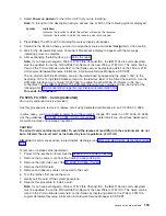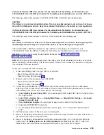
18.
The
cache
battery
pack
can
be
removed
from
the
2780
or
5708
card
without
removing
the
card
from
the
system.
Perform
the
following
to
ensure
all
cache
data
is
written
to
disk
before
battery
replacement:
a.
Select
System
Service
Tools
(SST)
.
If
you
cannot
get
to
SST,
select
DST.
But
do
not
perform
an
IPL
to
get
to
DST.
b.
Select
Start
a
Service
Tool
—>
Display/Alter/Dump
—>
Display/Alter
storage
—>
Licensed
Internal
Code
(LIC)
data
.
c.
Select
Advanced
analysis
.
You
may
have
to
page
or
scroll
down
to
find
this
option.
d.
Select
the
BATTERYINFO
command.
e.
On
the
Specify
Advanced
Analysis
Options
screen,
type
-LIST
in
the
Options
field
and
press
Enter.
19.
Find
the
resource
name
of
the
card
you
are
working
with.
Note:
The
″
Concurrently
Maintainable
Battery
Pack
″
field
should
indicate
″
yes.
″
If
it
does
not
indicate
″
yes,
″
then
discontinue
this
procedure
and
contact
your
next
level
of
support.
20.
Return
to
the
Specify
Advanced
Analysis
Options
screen
and
type
-CONFR
-IOA
xxxx
,
where
xxxx
is
the
card
resource
name.
21.
Return
to
the
Specify
Advanced
Analysis
Options
screen
and
type
-LIST
in
the
Options
field
and
press
Enter.
Note:
The
″
Battery
pack
can
be
safely
replaced
″
field
should
indicate
″
yes.
″
If
it
does
not
indicate
″
yes,
″
then
discontinue
this
procedure
and
contact
your
next
level
of
support.
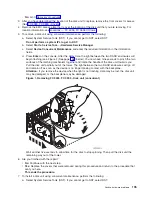
22.
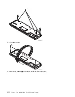
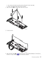
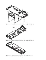
Use
the
following
illustration
to
locate
the
metal
cover
(
A
)
that
holds
the
battery
pack.
Pull
out
on
the
push-rivet
to
release
the
metal
cover.
206
Hardware
(Remove
and
Replace;
Part
Locations
and
Listings)
Содержание 270
Страница 2: ......
Страница 12: ...x Hardware Remove and Replace Part Locations and Listings...
Страница 279: ...Figure 3 CCIN 2881 with pluggable DIMM Analyze hardware problems 267...
Страница 281: ...Figure 6 Models 830 SB2 with FC 9074 HSL and SPCN locations Analyze hardware problems 269...
Страница 283: ...Figure 1b Model 840 SB3 processor tower dual line cord Analyze hardware problems 271...
Страница 294: ...01 gif port and LED locations 282 Hardware Remove and Replace Part Locations and Listings...
Страница 295: ...s src rzaq4519 gif locations Analyze hardware problems 283...
Страница 318: ...Figure 2 FC 5088 FC 0588 Expansion I O Unit top view 306 Hardware Remove and Replace Part Locations and Listings...
Страница 415: ...Table 2 Final assembly rear Models 830 and SB2 with FC 9074 continued Analyze hardware problems 403...
Страница 422: ...Table 1 Cover assembly Models 840 and SB3 processor tower 410 Hardware Remove and Replace Part Locations and Listings...
Страница 483: ...Table 1 Cover assembly FC 5095 Expansion I O Tower Analyze hardware problems 471...
Страница 505: ...Table 15 Model 830 SB2 System Unit with FC 9074 Power cables single line cord Analyze hardware problems 493...
Страница 511: ...Table 19 Model 840 SB3 Processor Tower Power cables single line cord Analyze hardware problems 499...
Страница 513: ...Table 21 Model 840 and Model SB3 9079 Base I O Tower Power cables dual line cord Analyze hardware problems 501...
Страница 519: ...Figure 15 Models 870 and 890 Primary I O to CEC interconnection part 1 Analyze hardware problems 507...
Страница 614: ...602 Hardware Remove and Replace Part Locations and Listings...
Страница 618: ...606 Hardware Remove and Replace Part Locations and Listings...
Страница 621: ......
Страница 622: ...Printed in USA SY44 5917 02...


