


1.
Determine
if
the
system
has
logical
partitions.
Go
to
before
continuing
with
this
procedure.
2.
Remove
media
(if
any)
from
the
device.
If
the
eject
button
on
a
tape
device
is
failing,
go
to
then
continue
with
the
next
step
of
this
procedure.
If
the
eject
button
on
a
CD-ROM
is
failing
and
will
not
open,
go
to
and
then
continue
with
the
next
step
of
this
procedure.
If
the
eject
button
on
a
DVD-RAM
is
failing
and
will
not
open,
do
not
attempt
to
manually
remove
the
optical
media
at
this
point
in
time.
3.
Are
you
removing
a
unit
by
using
device
concurrent
maintenance?
v
Yes
:
Continue
with
the
next
step.
v
No
:
Perform
the
following:
a.
Power
off
the
expansion
tower.
See
b.
Disconnect
the
power
cord
from
the
expansion
tower.
c.
Open
the
front
cover.
See
d.
Pull
on
the
handles
which
are
located
on
each
side
of
the
unit
and
remove
the
unit.
e.
Install
the
new
device
by
reversing
the
remove
procedure.
After
exchanging
an
item,
go
to
Notes:
–
If
you
need
to
remove
a
tape
from
the
old
tape
unit,
see
–
If
you
need
to
remove
optical
media
from
a
DVD-RAM
unit,
go
to
This
ends
the
procedure.
4.
Before
exchanging
a
removable
media
unit,
you
must
ensure
that
the
unit
is
not
in
use
and
is
varied
off.
Note:
If
you
are
removing
an
optical
storage
unit
you
must
ensure,
that
all
of
the
removable
media
units
in
the
expansion
tower
are
not
in
use
and
are
varied
off.
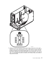
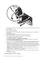
5.
Use
the
figure
to
determine
the
location
of
the
internal
removable
media
unit.
Record
this
location
for
later
use.
Figure
1.
Internal
removable
media
locations
6.
Perform
the
following:
a.
Select
System
Service
Tools
(SST).
If
you
cannot
get
to
SST,
select
DST.
Do
not
perform
a
system
IPL
to
get
to
DST.
b.
Select
Start
a
Service
Tool
—>
Hardware
Service
Manager
.
c.
Select
Device
Concurrent
Maintenance
and
enter
the
required
information
in
the
information
fields.
Do
not
press
the
Enter
key
at
this
time.
d.
Read
the
remaining
steps
of
this
procedure
and
ensure
that
you
understand
the
procedure
before
continuing.
e.
Press
Enter
on
the
console.
After
the
delay
time,
the
light
at
the
top
right
of
the
device
will
begin
flashing.
You
now
have
9
seconds
to
pull
out
firmly
on
the
handles
and
pull
the
unit
partially
out
of
the
tower.
The
light
at
the
top
right
of
the
device
will
go
off
and
remain
off
as
soon
as
the
device
is
no
longer
making
contact
with
the
backplane.
Attention:
If
you
remove
the
device
when
the
light
is
not
flashing,
data
may
be
lost,
the
unit
may
be
damaged,
or
the
backplane
may
be
damaged.
Analyze
hardware
problems
69
Содержание 270
Страница 2: ......
Страница 12: ...x Hardware Remove and Replace Part Locations and Listings...
Страница 279: ...Figure 3 CCIN 2881 with pluggable DIMM Analyze hardware problems 267...
Страница 281: ...Figure 6 Models 830 SB2 with FC 9074 HSL and SPCN locations Analyze hardware problems 269...
Страница 283: ...Figure 1b Model 840 SB3 processor tower dual line cord Analyze hardware problems 271...
Страница 294: ...01 gif port and LED locations 282 Hardware Remove and Replace Part Locations and Listings...
Страница 295: ...s src rzaq4519 gif locations Analyze hardware problems 283...
Страница 318: ...Figure 2 FC 5088 FC 0588 Expansion I O Unit top view 306 Hardware Remove and Replace Part Locations and Listings...
Страница 415: ...Table 2 Final assembly rear Models 830 and SB2 with FC 9074 continued Analyze hardware problems 403...
Страница 422: ...Table 1 Cover assembly Models 840 and SB3 processor tower 410 Hardware Remove and Replace Part Locations and Listings...
Страница 483: ...Table 1 Cover assembly FC 5095 Expansion I O Tower Analyze hardware problems 471...
Страница 505: ...Table 15 Model 830 SB2 System Unit with FC 9074 Power cables single line cord Analyze hardware problems 493...
Страница 511: ...Table 19 Model 840 SB3 Processor Tower Power cables single line cord Analyze hardware problems 499...
Страница 513: ...Table 21 Model 840 and Model SB3 9079 Base I O Tower Power cables dual line cord Analyze hardware problems 501...
Страница 519: ...Figure 15 Models 870 and 890 Primary I O to CEC interconnection part 1 Analyze hardware problems 507...
Страница 614: ...602 Hardware Remove and Replace Part Locations and Listings...
Страница 618: ...606 Hardware Remove and Replace Part Locations and Listings...
Страница 621: ......
Страница 622: ...Printed in USA SY44 5917 02...


