


Models
270,
800,
and
810
-
Disk
unit
(dedicated)
For
use
by
authorized
service
providers.
Use
this
procedure
to
remove
or
replace
a
disk
unit
using
dedicated
maintenance
on
the
Models
270,
800,
and
810.
The
Models
270,
800,
and
810
may
be
housed
in
a
FC
0551
frame.
The
upper
and
lower
system
units
are
placed
on
rails
in
the
frame.
If
you
are
working
on
the
upper
or
lower
unit,
follow
these
instructions
and
access
the
internal
parts
by
opening
the
front
cover
and
sliding
the
system
unit
out
on
its
rails.
Attention:
The
disk
unit
is
sensitive
to
electrostatic
discharge.
See
To
remove
or
replace
the
disk
unit
using
dedicated
maintenance:
1.
Determine
if
the
system
has
logical
partitions.
Go
to
before
continuing
with
this
procedure.
2.
Were
you
directed
here
from
v
Yes
:
Continue
with
the
next
step.
v
No
:
Go
to
3.
To
remove
a
disk
unit
using
dedicated
maintenance,
perform
the
following:
a.
Power
off
the
system.
See
b.
Disconnect
the
power
cord.
On
Models
270,
800,
and
810
with
a
system
unit
expansion
attached,
disconnect
both
the
system
line
cord
and
the
expansion
unit
line
cord.
c.
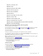
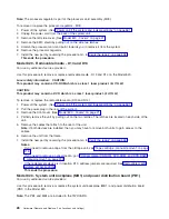
To
remove
the
disk
unit,
pinch
the
two
surfaces
of
the
latching
mechanism
together
and
pull
the
handle
towards
you
to
release
the
disk
unit
from
the
slot.
d.
Remove
the
unit.
Figure
1.
Removing
a
disk
unit
-
dedicated
4.
Are
you
finished
with
the
repair?
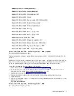
Analyze
hardware
problems
11
Содержание 270
Страница 2: ......
Страница 12: ...x Hardware Remove and Replace Part Locations and Listings...
Страница 279: ...Figure 3 CCIN 2881 with pluggable DIMM Analyze hardware problems 267...
Страница 281: ...Figure 6 Models 830 SB2 with FC 9074 HSL and SPCN locations Analyze hardware problems 269...
Страница 283: ...Figure 1b Model 840 SB3 processor tower dual line cord Analyze hardware problems 271...
Страница 294: ...01 gif port and LED locations 282 Hardware Remove and Replace Part Locations and Listings...
Страница 295: ...s src rzaq4519 gif locations Analyze hardware problems 283...
Страница 318: ...Figure 2 FC 5088 FC 0588 Expansion I O Unit top view 306 Hardware Remove and Replace Part Locations and Listings...
Страница 415: ...Table 2 Final assembly rear Models 830 and SB2 with FC 9074 continued Analyze hardware problems 403...
Страница 422: ...Table 1 Cover assembly Models 840 and SB3 processor tower 410 Hardware Remove and Replace Part Locations and Listings...
Страница 483: ...Table 1 Cover assembly FC 5095 Expansion I O Tower Analyze hardware problems 471...
Страница 505: ...Table 15 Model 830 SB2 System Unit with FC 9074 Power cables single line cord Analyze hardware problems 493...
Страница 511: ...Table 19 Model 840 SB3 Processor Tower Power cables single line cord Analyze hardware problems 499...
Страница 513: ...Table 21 Model 840 and Model SB3 9079 Base I O Tower Power cables dual line cord Analyze hardware problems 501...
Страница 519: ...Figure 15 Models 870 and 890 Primary I O to CEC interconnection part 1 Analyze hardware problems 507...
Страница 614: ...602 Hardware Remove and Replace Part Locations and Listings...
Страница 618: ...606 Hardware Remove and Replace Part Locations and Listings...
Страница 621: ......
Страница 622: ...Printed in USA SY44 5917 02...