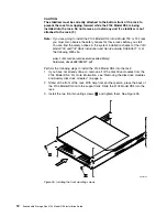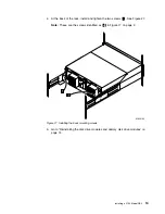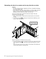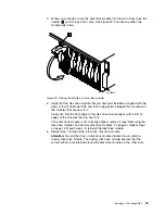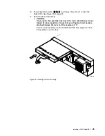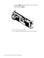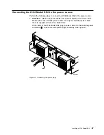
Installing
the
switch
cover
plate
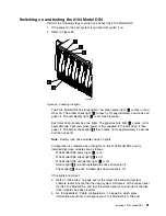
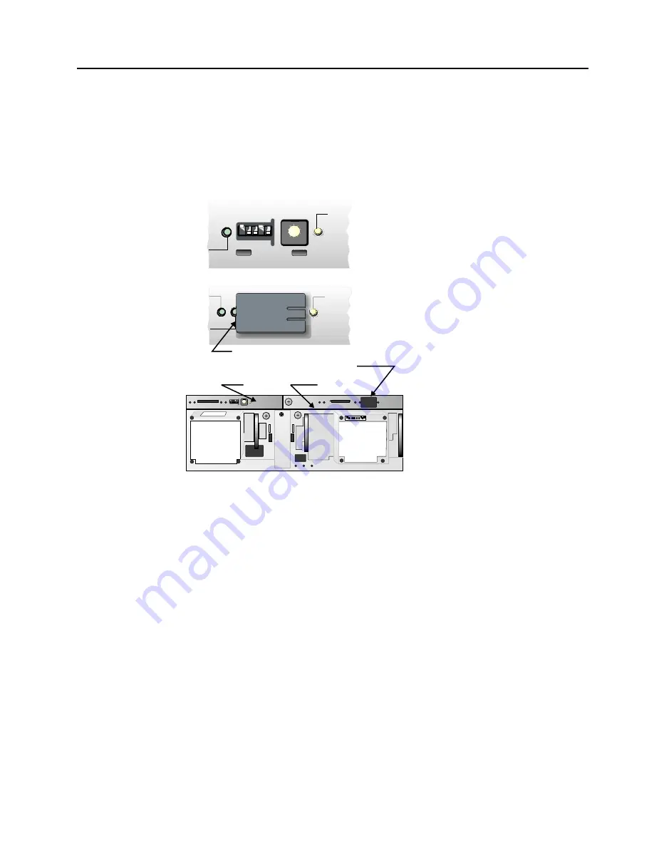
Note:
Switch
configuration
is
only
valid
on
the
SCSI
interface
card-1,
which
is
on
the
left
side
(left
side
from
the
rear
view).
The
configuration
on
the
SCSI
interface
card-2,
which
is
on
the
right
side,
is
ignored.
The
switch
cover
plate
is
on
card-2
so
that
it
can
be
masked.
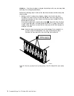
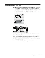
See
Figure
31.
You
must
place
the
SCSI
interface
card
in
the
left
side
from
the
rear
view
in
a
single
SCSI
interface
card
configuration.
See
JBOD
1
in
Figure
31.
Perform
the
following
steps
to
install
the
switch
cover
plate
onto
the
panel
of
the
SCSI
Interface
card-2
(second
JBOD
interface
card).
Note:
If
the
switch
cover
plate
is
already
installed,
you
do
not
need
to
perform
step
1
through
step
3
on
page
18.
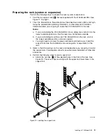
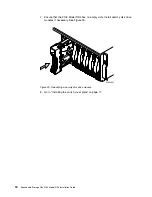
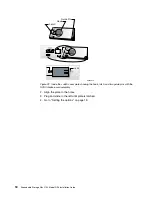
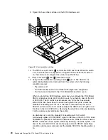
1.
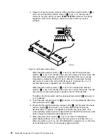
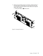
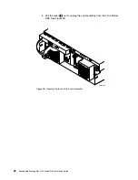
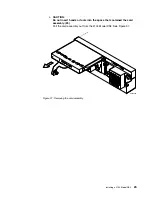
Locate
the
hook,
latch,
and
pins.
See
Figure
32
on
page
18.
SC000277
CARD
CAR
5 4 3 2 1
1
2
3
45
6
7
8
9 0
OPTION
SWITCH
UNIT ID
JBOD 2
Switch Cover plate
SW Cover added on 2nd JBOD card
JBOD 1
5 4 3 2 1
1
2
3
45
6
7
8
9 0
OPTION
SWITCH
UNIT ID
Figure
31.
Installing
the
switch
cover
plate
onto
the
panel
of
the
SCSI
Interface
card-2
(second
JBOD
interface
card)
box
Installing
a
2104
Model
DS4
17
Содержание 2104 Model DS4
Страница 2: ......
Страница 3: ...Expandable Storage Plus 2104 Model DS4 Installation Guide GA22 1053 00 ...
Страница 9: ...Tables 1 Valid configurations 37 Copyright IBM Corp 2003 vii ...
Страница 10: ...viii Expandable Storage Plus 2104 Model DS4 Installation Guide ...
Страница 30: ...xxviii Expandable Storage Plus 2104 Model DS4 Installation Guide ...
Страница 90: ...58 Expandable Storage Plus 2104 Model DS4 Installation Guide ...
Страница 98: ...66 Expandable Storage Plus 2104 Model DS4 Installation Guide ...
Страница 101: ......
Страница 102: ... Part Number 97P1535 Printed in USA GA22 1053 00 1P P N 97P1535 ...
Страница 103: ...Spine information Expandable Storage Plus Expandable Storage Plus 2104 Model DS4 Installation Guide ...

