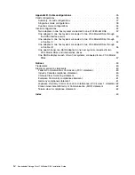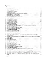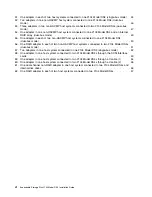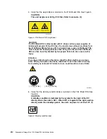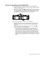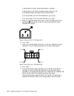
Figures
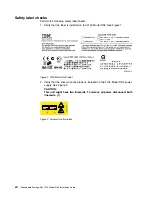
1.
2104
Model
DS4
label
.
.
.
.
.
.
.
.
.
.
.
.
.
.
.
.
.
.
.
.
.
.
.
.
.
.
.
.
. xii
2.
Linecord
caution
label
.
.
.
.
.
.
.
.
.
.
.
.
.
.
.
.
.
.
.
.
.
.
.
.
.
.
.
.
. xii
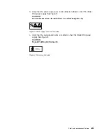
3.
Power
supply
cover
caution
label
.
.
.
.
.
.
.
.
.
.
.
.
.
.
.
.
.
.
.
.
.
.
.
.
. xiii
4.
Fusing
caution
label
.
.
.
.
.
.
.
.
.
.
.
.
.
.
.
.
.
.
.
.
.
.
.
.
.
.
.
.
.
. xiii
5.
2104
Model
DS4
weight
label
.
.
.
.
.
.
.
.
.
.
.
.
.
.
.
.
.
.
.
.
.
.
.
.
.
. xiv
6.
Standby
condition
label
.
.
.
.
.
.
.
.
.
.
.
.
.
.
.
.
.
.
.
.
.
.
.
.
.
.
.
. xiv
7.
Power
cables
and
SCSI
connectors
on
the
2104
Model
DS4
.
.
.
.
.
.
.
.
.
.
.
.
.
.
. xv
8.
Ground
pin
(220
V
2104
Model
DS4
)
.
.
.
.
.
.
.
.
.
.
.
.
.
.
.
.
.
.
.
.
.
.
. xvi
9.
Ground
pins
(-48
V
2104
Model
DS4)
.
.
.
.
.
.
.
.
.
.
.
.
.
.
.
.
.
.
.
.
.
.
. xvi
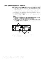
10.
Removing
the
power
from
a
2104
Model
DS4
.
.
.
.
.
.
.
.
.
.
.
.
.
.
.
.
.
.
.
. xviii
11.
Linecord
caution
label
.
.
.
.
.
.
.
.
.
.
.
.
.
.
.
.
.
.
.
.
.
.
.
.
.
.
.
.
. xxi
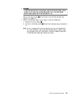
12.
Power
supply
cover
caution
label
.
.
.
.
.
.
.
.
.
.
.
.
.
.
.
.
.
.
.
.
.
.
.
.
. xxi
13.
Fusing
caution
label
.
.
.
.
.
.
.
.
.
.
.
.
.
.
.
.
.
.
.
.
.
.
.
.
.
.
.
.
. xxi
14.
2104
Model
DS4
weight
label
.
.
.
.
.
.
.
.
.
.
.
.
.
.
.
.
.
.
.
.
.
.
.
.
.
. xxii
15.
2104
Model
TS4
weight
label
.
.
.
.
.
.
.
.
.
.
.
.
.
.
.
.
.
.
.
.
.
.
.
.
.
. xxiii
16.
Location
of
standby
condition
.
.
.
.
.
.
.
.
.
.
.
.
.
.
.
.
.
.
.
.
.
.
.
.
.
. xxiv
17.
Items
for
the
2104
Model
DS4
.
.
.
.
.
.
.
.
.
.
.
.
.
.
.
.
.
.
.
.
.
.
.
.
.
. 2
18.
Installing
the
support
rails
.
.
.
.
.
.
.
.
.
.
.
.
.
.
.
.
.
.
.
.
.
.
.
.
.
.
.
. 3
19.
2104
Model
DS4
weight
label
.
.
.
.
.
.
.
.
.
.
.
.
.
.
.
.
.
.
.
.
.
.
.
.
.
. 5
20.
Disk
drive
modules
that
show
the
position
of
the
2104
Model
DS4
serial
number
label
.
.
.
.
.
. 6
21.
Opening
the
handle
of
a
disk
drive
module
.
.
.
.
.
.
.
.
.
.
.
.
.
.
.
.
.
.
.
.
.
. 7
22.
Removing
a
disk
drive
module
.
.
.
.
.
.
.
.
.
.
.
.
.
.
.
.
.
.
.
.
.
.
.
.
.
. 8
23.
Disk
drive
module
on
its
side
for
safe
storage
.
.
.
.
.
.
.
.
.
.
.
.
.
.
.
.
.
.
.
.
. 9
24.
Removing
a
dummy
disk
drive
module
.
.
.
.
.
.
.
.
.
.
.
.
.
.
.
.
.
.
.
.
.
.
. 10
25.
2104
Model
DS4
weight
label
.
.
.
.
.
.
.
.
.
.
.
.
.
.
.
.
.
.
.
.
.
.
.
.
.
. 11
26.
Installing
the
front
mounting
screws
.
.
.
.
.
.
.
.
.
.
.
.
.
.
.
.
.
.
.
.
.
.
.
. 12
27.
Installing
the
back
mounting
screws
.
.
.
.
.
.
.
.
.
.
.
.
.
.
.
.
.
.
.
.
.
.
.
. 13
28.
Reinstalling
a
2104
Model
DS4
disk
drive
module
.
.
.
.
.
.
.
.
.
.
.
.
.
.
.
.
.
.
. 14
29.
Closing
the
handle
of
a
disk
drive
module
.
.
.
.
.
.
.
.
.
.
.
.
.
.
.
.
.
.
.
.
. 15
30.
Reinstalling
a
dummy
disk
drive
module
.
.
.
.
.
.
.
.
.
.
.
.
.
.
.
.
.
.
.
.
.
. 16
31.
Installing
the
switch
cover
plate
onto
the
panel
of
the
SCSI
Interface
card-2
(second
JBOD
interface
card)
box
.
.
.
.
.
.
.
.
.
.
.
.
.
.
.
.
.
.
.
.
.
.
.
.
.
.
.
.
.
. 17
32.
Inside
the
switch
cover
plate
showing
the
hook,
latch,
and
two
guide
pins
with
the
SCSI
Interface
card
assembly
.
.
.
.
.
.
.
.
.
.
.
.
.
.
.
.
.
.
.
.
.
.
.
.
.
.
.
.
.
.
.
. 18
33.
Setting
the
box
ID
.
.
.
.
.
.
.
.
.
.
.
.
.
.
.
.
.
.
.
.
.
.
.
.
.
.
.
.
.
. 19
34.
Setting
the
option
switches
.
.
.
.
.
.
.
.
.
.
.
.
.
.
.
.
.
.
.
.
.
.
.
.
.
.
. 20
35.
Unscrewing
the
thumbscrew
.
.
.
.
.
.
.
.
.
.
.
.
.
.
.
.
.
.
.
.
.
.
.
.
.
. 21
36.
Opening
the
lever
on
the
card
assembly
.
.
.
.
.
.
.
.
.
.
.
.
.
.
.
.
.
.
.
.
.
. 22
37.
Removing
the
card
assembly
.
.
.
.
.
.
.
.
.
.
.
.
.
.
.
.
.
.
.
.
.
.
.
.
.
. 23
38.
Card
assembly
switches
.
.
.
.
.
.
.
.
.
.
.
.
.
.
.
.
.
.
.
.
.
.
.
.
.
.
.
. 24
39.
Inserting
the
card
assembly
.
.
.
.
.
.
.
.
.
.
.
.
.
.
.
.
.
.
.
.
.
.
.
.
.
.
. 25
40.
Closing
the
lever
on
the
card
assembly
.
.
.
.
.
.
.
.
.
.
.
.
.
.
.
.
.
.
.
.
.
. 26
41.
Connecting
the
power
plugs
.
.
.
.
.
.
.
.
.
.
.
.
.
.
.
.
.
.
.
.
.
.
.
.
.
.
. 27
42.
Checking
the
power
supply
switch
and
lights
.
.
.
.
.
.
.
.
.
.
.
.
.
.
.
.
.
.
.
. 28
43.
Plug
in
the
SCSI
signal
cable
.
.
.
.
.
.
.
.
.
.
.
.
.
.
.
.
.
.
.
.
.
.
.
.
.
. 29
44.
Back
of
fully
configured
2104
Model
DS4
after
connection
to
the
host
system
.
.
.
.
.
.
.
. 30
45.
Checking
the
lights
.
.
.
.
.
.
.
.
.
.
.
.
.
.
.
.
.
.
.
.
.
.
.
.
.
.
.
.
.
. 31
46.
One
adapter
in
one
host
system
connected
to
one
2104
Model
DS4
(single-bus
mode)
.
.
.
.
. 39
47.
Two
adapters
in
one
host
system
connected
to
two
2104
Model
DS4s
(single-bus
mode)
.
.
.
. 40
48.
One
adapter
in
each
of
two
host
systems
connected
to
two
2104
Model
DS4s
(single-bus
mode)
41
49.
One
adapter
in
one
host
system
connected
to
two
2104
Model
DS4s
(single-bus
mode)
.
.
.
. 42
50.
One
adapter,
one
host
system
with
internal
RAID
array,
and
two
2104
Model
DS4s
(single-bus
mode)
.
.
.
.
.
.
.
.
.
.
.
.
.
.
.
.
.
.
.
.
.
.
.
.
.
.
.
.
.
.
.
.
.
.
. 43
©
Copyright
IBM
Corp.
2003
v
Содержание 2104 Model DS4
Страница 2: ......
Страница 3: ...Expandable Storage Plus 2104 Model DS4 Installation Guide GA22 1053 00 ...
Страница 9: ...Tables 1 Valid configurations 37 Copyright IBM Corp 2003 vii ...
Страница 10: ...viii Expandable Storage Plus 2104 Model DS4 Installation Guide ...
Страница 30: ...xxviii Expandable Storage Plus 2104 Model DS4 Installation Guide ...
Страница 90: ...58 Expandable Storage Plus 2104 Model DS4 Installation Guide ...
Страница 98: ...66 Expandable Storage Plus 2104 Model DS4 Installation Guide ...
Страница 101: ......
Страница 102: ... Part Number 97P1535 Printed in USA GA22 1053 00 1P P N 97P1535 ...
Страница 103: ...Spine information Expandable Storage Plus Expandable Storage Plus 2104 Model DS4 Installation Guide ...


