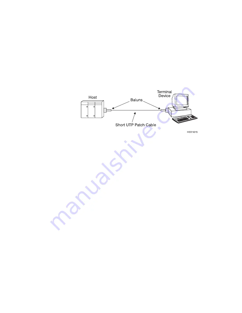
2. Attach a balun to the terminal and to the system host port. Use a short UTP
patch cable between the baluns, as shown in Figure 4-3. Repeat this step for
every balun and patch cable used.
If the host signon screen appears, the baluns and patch cords are okay.
Go to step 3.
If the host signon screen appears and then disappears, check for split
pairs. Split pairs use two conductors that are not a
twisted pair.
If no host signon screen appears, check the baluns and the UTP cable for:
– Faulty RJ plug crimping
– Incorrect plug type, which indicates that the cable is not straight wired
Figure 4-3. Attaching Baluns
3. Use a UTP patch cable to connect the host balun to the host input port of the
7299. Use a patch cable to connect the terminal balun to the device output
port of the 7299.
If the host signon screen appears, the 7299, the pinout, and the polarity
(phase) of all the components are okay. Go to step 4 on page 4-11.
If no host signon screen appears:
– Check the pinout and polarity of all cables and baluns. For information
about changing the pinout and polarity of the 7299, see “Changing the
Hub Polarity and Pinout Jumpers” on page 3-3.
For models 2EX and 2FX:
- When the host port pinout and polarity are correct, the host port
LED lights, indicating host polling.
- When the device port pinout and polarity are correct and an active
host is connected to the 7299, the device port LEDs light.
– For AS/400 hosts, check for a parity error on the host. The host and
devices are connected in your configuration, but poor electrical
connections, noise on cables, split pairs, and so on, could be causing
errors. For information about requesting functional tests, see “Potential
Problem Areas” on page 4-12.
4-10
Planning, Installation, and Maintenance Guide
Содержание 1PA
Страница 2: ......
Страница 8: ...vi Planning Installation and Maintenance Guide...
Страница 14: ...Planning Installation and Maintenance Guide...
Страница 29: ...This page intentionally left blank Chapter 2 Planning Your Installation 2 3...
Страница 30: ...Figure 2 1 7299 Multiplexer Address Worksheet 2 4 Planning Installation and Maintenance Guide...
Страница 31: ...Figure 2 2 7299 Multiplexer Address Worksheet Example Chapter 2 Planning Your Installation 2 5...
Страница 46: ...2 20 Planning Installation and Maintenance Guide...
Страница 72: ...Planning Installation and Maintenance Guide...
Страница 78: ...5 6 Planning Installation and Maintenance Guide...
Страница 86: ...6 8 Planning Installation and Maintenance Guide...
Страница 92: ...Planning Installation and Maintenance Guide...
Страница 100: ...B 6 Planning Installation and Maintenance Guide...
Страница 107: ......


