REFERENCE
This section of the manual provides information
which may be useful when installing SwingSmart
operators. It includes how to:
z
Connect a Radio Receiver for Remote Open
z
Install a Gate Locking Mechanism
z
Install Vehicle Detectors and Loops
z
Install Photoelectric Sensors
z
Install Gate Edge Sensors
z
Troubleshoot error codes, faults, and hardware
issues
z
Diagnose vehicle detector and loop faults
z
Handle General Maintenance issues
CONNECTING A RADIO RECEIVER FOR
REMOTE OPEN
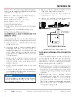
Take the following steps to mount a commercial
style 24VDC radio receiver (external antenna type):
1.
Install the receiver in the chassis on either side
of the control box.
2.
Route the wires to the area marked RADIO
OPTIONS. Only three wire connections are
needed because the common wire and one
radio output wire are connected together.
Figure 65 shows additional wires from a two
channel receiver.
3.
Make sure to observe polarity and crimp
together the black radio common wire and
one of the radio output wires using a ¼-inch
spade connector.
4.
Fasten the two crimped wires to the COM
terminal.
5.
Connect the red wire to the +24V spade and
connect the other radio output contact wire to
the spade marked OPEN.
NOTICE
This terminal is the same as the input terminal
labeled RADIO OPEN along the left edge of
the Smart DC Controller.
6.
Mount an external antenna onto the top of a
fixed fence post near the operator.
7.
Connect the antenna into the socket on the
radio receiver.
8.
Set the “DIP” switches in the receiver to match
the same code used in the transmitter.
Figure 65. Radio Receiver Connections
INSTALLING A MAGLOCK OR SOLENOID
LOCK
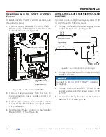
To provide additional gate security, a maglock or
a solenoid lock can be used and connected to
the Smart DC Controller. The Smart DC Controller
releases the lock prior to initiating gate movement.
Before installing the lock, be sure to:
z
Determine the electrical power requirements of
your lock (maglock or solenoid lock). Electronic
board and peripheral connections differ
between high voltage and lower voltage gate
operators.
z
Determine the current required. A total
combined current draw of 1 amp is available
from the 24VDC or 12VDC power supply. If the
peripherals attached to the terminals need more
than 1 amp, a separate power supply is required.
Refer to "Overview of the Smart DC Controller"
on page 84 and Figure 49
.
DUAL GATE
COM
COM
A
B
RADIO OPTIONS
OPEN +24V S1
SENSOR 1
SENSOR
COM
+ 24 V
EMERG
OPEN
SHOW
LEDs
U
SE
R2
COM NO
DC
Two Channel Radio Receiver
Power
Shows connecons
for Remote Open.
R1
108
| www.hysecurity.com
SWINGSMART DC PROGRAMMING AND OPERATIONS MANUAL
MX3640-01 REV. D ©2018
Содержание SwingSmart DC 20
Страница 2: ...2 www hysecurity com SWINGSMART DC PROGRAMMING AND OPERATIONS MANUAL MX3640 01 REV D 2018...
Страница 24: ...SAFETY INFORMATION 24 www hysecurity com SWINGSMART DC PROGRAMMING AND OPERATIONS MANUAL MX3640 01 REV D 2018...
Страница 138: ...NOTES 138 www hysecurity com SWINGSMART DC PROGRAMMING AND OPERATIONS MANUAL MX3640 01 REV D 2018...
Страница 139: ...NOTES 139 www hysecurity com SWINGSMART DC PROGRAMMING AND OPERATIONS MANUAL MX3640 01 REV D 2018...

