background image

INSTALLATION

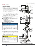
GATE BRACKET AND LINKAGE ARMS

Installing the Gate Bracket

1. 

Secure the gate to prevent movement.

2. 

Determine  the  proper  position  of  the  gate 

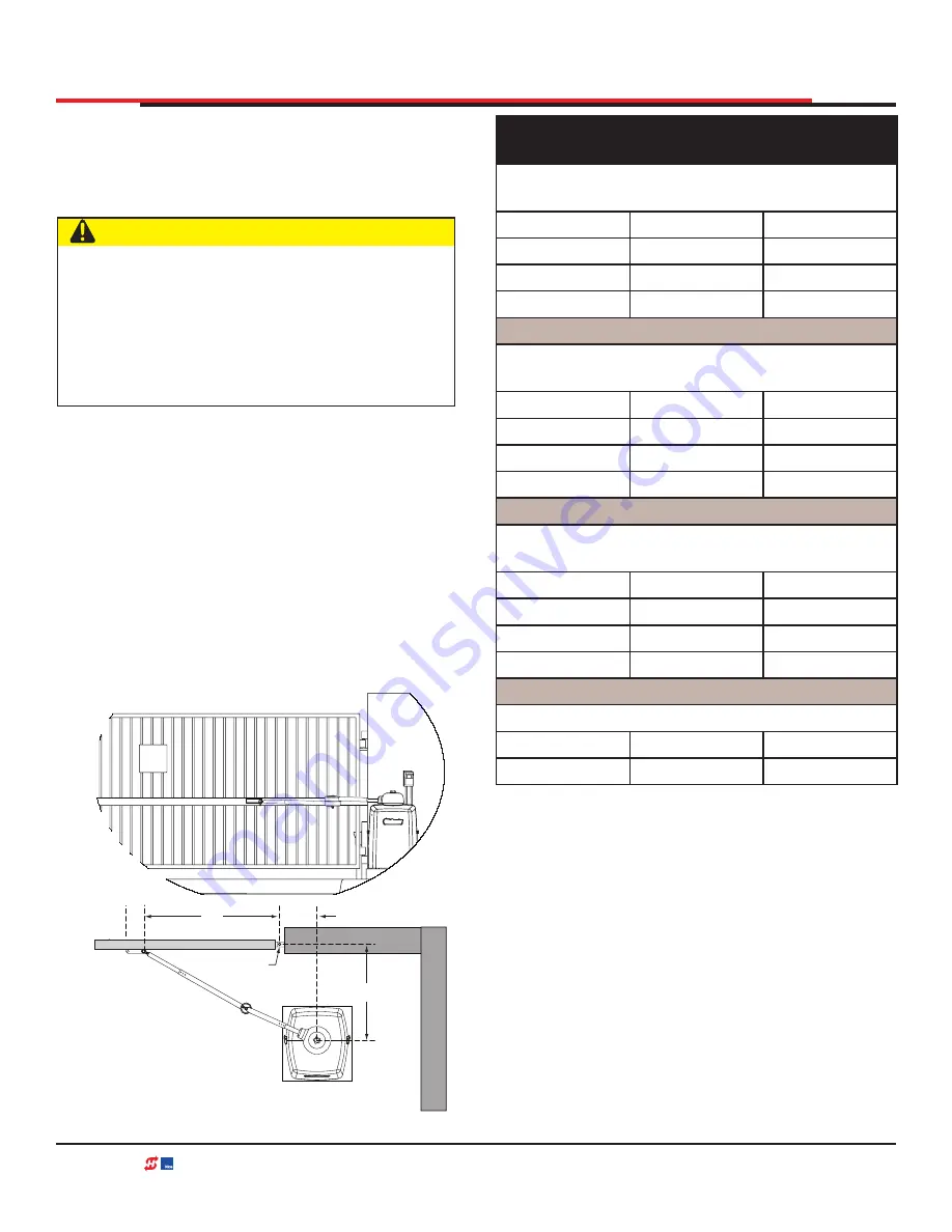
bracket. Use Figure 6 and Table 2 for reference.


Hint:

 Determine if you have a short, medium, 

or long gate. If the X and Y dimensions in the 

chart are the same as your install, set the gate 

bracket at the Xg dimension. If your install does 

not fit to the chart specs, use the Custom Gate 

Installation formula to determine the proper 

gate bracket placement.

3. 

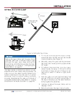
Measure and position the gate bracket so it is 

level with the arm on the operator. Clamp the 

gate bracket to the horizontal cross member.

Figure 6. Installing the Gate Bracket

  CAUTION

Consider positioning the operator so existing 

conduit  exits  through  the  cutout  in  the 

SwingSmart  base  plate.  Cutting  small  holes 

in  the  base  plate  for  pre-existing  conduit  is 

permissible, but not recommended because 

it can impair the strength of the chassis and 

void the Limited Warranty.

Hinge Center

X

Xg

Y

Table 2. Gate Bracket Installation 

Dimensions

Short Gate Installation:


For gates up to 10 feet (3 meters)

X

Y

Xg

10.5" (27cm)

14" (36cm)

23.5" (60cm)

18" (46cm)

27.5" (70cm)

20" (51cm)

29.5" (75cm)

Medium Gate Installation:


For gates up to 13 feet (4 meters)

X

Y

Xg

12" (31cm)

22" (56cm)

33" (84cm)

24" (61cm)

35" (89cm)

28" (71cm)

39" (99cm)

Long Gate Installation:


For gates up to 20 feet (6 meters)

X

Y

Xg

15" (38cm)

30" (76cm)

44" (112cm)

35" (89cm)

49" (124cm)

40" (101cm)

54" (137cm)

Custom Gate Installation:

X

Y

Xg

X + Y - 1

29 

| www.hysecurity.com 

SWINGSMART DC PROGRAMMING AND OPERATIONS MANUAL 

MX3640-01 REV. D  ©2018

Содержание SwingSmart DC 20

Страница 1: ...DC20 DCS20 Programming and Operations Manual Pad mounted electromechanical swing gate operator with Smart DC Controller Industrial Commercial Crash Parking Residential 800 321 9947 253 867 3700 www h...

Страница 2: ...2 www hysecurity com SWINGSMART DC PROGRAMMING AND OPERATIONS MANUAL MX3640 01 REV D 2018...

Страница 3: ...RAMMING AND OPERATIONS MANUAL MX3640 01 REV D 2018 SWINGSMART DC 20 GATE OPERATOR SWINGMART DCS 20 GATE OPERATOR PROGRAMMING AND OPERATIONS MANUAL MX3640 01 REVISION D HYSECURITY CORPORATE HEADQUARTER...

Страница 4: ...115VAC Power 41 Wiring 208 230VAC Power 42 Connecting DC Power 43 Using a Solar Powered Operator 43 Design Requirements Considerations 44 Connecting the SwingSmart DCS 20 to Solar Power Panels 45 Con...

Страница 5: ...ntrols 103 Software Maintenance 103 Electrical Controls 103 Clock Battery Replacement 103 Fuse Replacement 104 Mechanical Maintenance 104 Drive Belt Tension and Alignment 105 DC Battery Replacement 10...

Страница 6: ...juststhegatespeedtosynchronize the left and right gates so that they reach the open and close positions at the same time Independent leaf delay adjustment for bi parting gates is selectable in second...

Страница 7: ...Cover Cover Pulley Motor Motor Brush Kit Battery Kit 50AH Battery Kit 8AH Handle Clamp Clamp Assembly Limit Plate Blocks Limit Switch Kit Bracket Limit Swith Knob Top Cover Detector Vehicle MX4535 SE...

Страница 8: ...Complete Initial Setup Menu programming Review the connections on the Smart DC Controller Install Primary Secondary operator connections if the site is a bi parting gate system Attach accessory devic...

Страница 9: ...SAFETY SYMBOLS DANGER Indicates a hazardous situation which if not avoided WILL result in DEATH or SERIOUS INJURY WARNING Indicates a hazardous situation which if not avoided COULD result in DEATH or...

Страница 10: ...death Start gate operator only when the gate s travel path is clear 2 Never let children operate or play with gate controls Keep all remote controls especially radio transmitters away from children D...

Страница 11: ...maged gate Make sure all exposed pinch points rollers and wheels are guarded Reduce entrapment risk throughout entire travel path make sure gate is installed in a location so enough clearance is suppl...

Страница 12: ...tes are for vehicular use only provide and maintain walkways and signs to direct pedestrians to a separate walk through entrance An automatic gate can start at any time without warning always keep peo...

Страница 13: ...n and safety decals when they become dif cult read Manufacturer does not assume responsibility for any accident due to equipment modi cations Unauthorized equipment modi cation will void all warrantie...

Страница 14: ...d state of the art Absorbed Glass Mat AGM batteries and highly recommends replacing used batteries with new AGM type batteries To reduce risk of re or injury to persons Observe polarity between batter...

Страница 15: ...al and plastic recycling center promotes energy cost savings EXTERNAL ENTRAPMENT PROTECTION SENSORS Most HySecurity gate operators are equipped with a Type A Inherent Entrapment Sensor IES UL 325 Safe...

Страница 16: ...al is not impeded by building structures or other obstructions All sensors must be installed so that they function as intended for end use conditions UL 325 LISTING Edge sensors and photo electric eye...

Страница 17: ...ch as a multi family housing units ve or more single family units hotels garages retail stores or other buildings servicing general public Class III Class III Intended for use in an industrial locatio...

Страница 18: ...ng B1 install non contact sensors photoelectric sensor or equivalent according to instructions To comply using B2 install contact sensors edge sensor device or equivalent according to instructions To...

Страница 19: ...perator s motor runs or is always powered when the operator is connected to AC power Table 1 Sensors Tested for Use with HySecurity Operators Mfg Part Mfg Details Hysecurity Part Photo Eyes Retrore ec...

Страница 20: ...pear CAUTION EMX IRB MON Photo Eye Transmitter CAUTION Set DIP Switches 1 OFF 2 OFF 3 OFF 4 ON NOTE DIP switches mustbe set as shown otherwise the photo eye will not operate correctly Jumper POWER INP...

Страница 21: ...nd Leading End PUBLIC SECURE 5 4 3 2 1 6 Swing Gate Potential Zones for Entrapment Protection 1 Leading Edge 2 Bottom Edge 3 Entry Exit 4 Posts 5 Post Pivot Pinch Points 6 Arm Movement SECURE PUBLIC I...

Страница 22: ...t maximum wind speed in areas around the United States search for US government wind speed maps on the internet If you don t know how to calculate for wind load ask a mechanical engineer or site archi...

Страница 23: ...allows a gate to be pushed manually when the taper clamp is loosened It is recommended that you turn off DC power which disengages the motor allowing you to easily move the gate When you turn DC power...

Страница 24: ...SAFETY INFORMATION 24 www hysecurity com SWINGSMART DC PROGRAMMING AND OPERATIONS MANUAL MX3640 01 REV D 2018...

Страница 25: ...pproximately 10 to 15 seconds Variable speed open close separately Gate weight 1 300lbs 12ft leaf 590kg 4m leaf 1 300lbs 12ft leaf 590kg 4m leaf Secure Side Public Side WARNING Pedestrian gate Make su...

Страница 26: ...e design also provides a 9 6 inch 24 4cm height between the control box and chassis base for pulling and placement of wires CAUTION Be sure to restrict conduit to the 6 x 7 inch 15 2 x 17 7cm cutout i...

Страница 27: ...ng conduit is permissible but not recommended because it can impair the strength of the chassis and void the Limited Warranty UNPACKING THE OPERATOR Prepare the gate operator for installation See Figu...

Страница 28: ...Y dimension at 30 35 or 40 76 89 or 102cm 3 Set the operator base on the concrete pad and use it as a template Position the operator base so the center mark on the pad aligns with the small hole in th...

Страница 29: ...Bracket CAUTION Consider positioning the operator so existing conduit exits through the cutout in the SwingSmart base plate Cutting small holes in the base plate for pre existing conduit is permissibl...

Страница 30: ...he taper clamp assembly using the fasteners removed in step 2 4 Pull the taper handle to lengthen it Adjust the handle so the ball detent fits into its cutout and secures the handle length Turn the ha...

Страница 31: ...nches 121cm A B INSTALLATION Table 3 Gate Linkage Arms Installation Dimensions Short Gate Installation For gates up to 10 feet 3 meters X Y Xg A B 10 5 27cm 14 36cm 23 5 60cm 15 5 39cm 21 5 55cm 18 46...

Страница 32: ...71cm 40 5 103cm 120 32 81cm 20 51cm 41 104cm 31 5 80cm 44 112cm 130 38 97cm 18 46cm 44 112cm 36 91cm 47 5 121cm NOTE Maximum A 38 97cm NOTE Maximum B 47 5 121cm NOTICE The linkage tubes used for the...

Страница 33: ...If the pivot bolt is not vertical binding of the arm assembly may occur during operation Set screw The set screw serves as a physical stop when the gate is closed Middle set screw hole allows a slight...

Страница 34: ...djust the limit cams use a Phillips head screwdriver and loosen the fastener that secures each limit cam to the limit plate 3 Manually open and close the gate Move the limit cams so they trip the appr...

Страница 35: ...g the elbow with a slight offset at the full close position Use the supplied set screw in middle position to prevent the arm from locking The intent of the offset is that upon gate strike the elbow wi...

Страница 36: ...es not recommend it The preferred method is an installation where the gate arm remains horizontal throughout gate travel z z A gate must be neutrally balanced To comply with ASTM F2200 General Require...

Страница 37: ...ting the taper clamp until after the operator has been configured to run Refer to Configuring the Setup Menu on page 55 1 To loosen and release the taper clamp extend the taper handle and turn the han...

Страница 38: ...nds the motor turns off and the buzzer continues for another 30 seconds ALERT 1 FORCED OPEN appears on the display An OPEN or CLOSE command clears the alert and resets the display z z Fully straighten...

Страница 39: ...E Properly grounding the gate operator is critical to gate operator performance and the life of its electrical components Use sufficient wire size during installation If you do not ground the operator...

Страница 40: ...ed to the 230V position or damage to the operator will occur and void the Limited Warranty Figure 18 Wiring AC Power Voltage selector switch is factory set to 115V If power input is 208 230V move the...

Страница 41: ...t the wire size be increased or the distance of the run be decreased To connect to 115VAC power take the following steps 1 Make sure the AC power is turned off at its source and the DC and AC power sw...

Страница 42: ...tection cover and secure it NOTICE Table 6 assumes a dedicated circuit Additional loads require that the wire size be increased or the distance of the run be decreased 4 Access the input power wires b...

Страница 43: ...harger which allows a 24V solar panel or two 12V panels a direct connection to the SwingSmart operator with no additional electronic devices required To plan a solar powered site read through this ent...

Страница 44: ...teries z z Solar hours at the site Solar hours relate to the amount of energy delivered by the sun and absorbed by the solar panels It is NOT the same as the number of daylight hours available at the...

Страница 45: ...crimp bond the equipment ground wire to the green ground wire in the junction box 6 Slide the plastic cover off the control box and attach the red spade connector to the battery terminal on the upper...

Страница 46: ...Solid state 24VDC 24VDC 12VDC 12VDC Press button to light active inputs COM B A DUAL GATE COM OPEN 24V RADIO OPTIONS S1 COM NO USER2 DC Amp Draw on Power Supplies Two power supplies are available 24V...

Страница 47: ...which usually draw at minimum 0 009A Understanding Gate Activity based on Solar Zones Use the solar maps to determine the number of solar hours per day that can be reasonably expected in a particular...

Страница 48: ...with the gate travel occurring throughout the night determines the battery capacity required The number of amps that the peripherals draw coupled with the gate travel during the day determines the so...

Страница 49: ...tteries contain sulfuric acid Acid in your eyes on your skin or on your clothing can cause injury and severe burns If batteries are dropped or damaged dispose of them properly POWER z z Batteries are...

Страница 50: ...fully rotate the support tray to access the battery wires Lift the 8Ah batteries from the support tray Disconnect the black and blue wires and set the 8Ah batteries aside 6 Return the support tray to...

Страница 51: ...1 Start at a gate status display 2 To access the User Menu press the MENU button twice 3 Access the Installer Menu by simultaneously pressing the OPEN and RESET buttons 4 Use NEXT to navigate to the...

Страница 52: ...into the field A S T A R T User Guide is also available online CAUTION Smart DC Controller can be powered when either switch is turned on The operator is a DC powered unit and runs on its batteries If...

Страница 53: ...the Setup Menu z z Error message indicates a problem exists with the operator which needs to be resolved before the operator can function properly Left Handing Right Handing NOTICE If AC power is los...

Страница 54: ...he RESET button or cycling power Faults indicate a need for diagnosis and resolution Refer to Smart DC Controller Troubleshooting on page 123 Figure 30 Function of the Smart DC Controller Buttons in M...

Страница 55: ...Menu Refer to Reinstating Factory Defaults on page 82 Figure 31 Configuring the Setup Menu SH 0 GATE HANDING OPEN CLOSE STOP MENU RESET PREV NEXT SELECT UC 0 USAGE CLASS OPEN CLOSE STOP MENU RESET PRE...

Страница 56: ...ressing Open Close or Stop causes the gate to perform the command Pressing Reset clears alerts or faults and returns to Run Mode NOTE Press Reset at any Run mode status display to view the software ve...

Страница 57: ...a dual gate setting whether operator is set to Primary or Secondary Setting is assigned in Installer Menu Operator Type OT OT 12 SwingSmart DC or DCS Indicates and identifies the operator Set Handing...

Страница 58: ...e not counted Displays number of cycles gate operator has incurred Similar to an odometer it resets to zero after 999 999 cycles Close Timer CT The first menu item in the User Menu See User Menu on pa...

Страница 59: ...st be in Run Mode The motor cannot be engaged and the gate cannot be moving ADJUSTING THE CLOSE TIMER The close timer assigns how many seconds will pass before the operator initiates automatic closure...

Страница 60: ...s on the date and time display press SELECT 8 To exit the User Menu press the MENU button A gate status appears in the display indicating you have returned to Run Mode NOTICE A date or time field must...

Страница 61: ...open or close command is ignored and LCD appears blank System remains in this disabled state until reset or battery recovers to 24V AP 2 AC LOSS AUTO OPEN Operator automatically opens gate five second...

Страница 62: ...E TIMER display appears 2 Press NEXT until the LCD CONTRAST display appears 3 Use the SELECT and NEXT buttons to navigate and change the number on the display 4 To exit the User Menu press the MENU bu...

Страница 63: ...matic close timer and causes its menu to disappear You must set HC to 1 to comply with UL 325 Type D protection Refer to Table Notes COM CLOSE HO 0 OFF Hold to Open 0 off 1 on SimilartoHOLDTOCLOSE but...

Страница 64: ...death FA 0 OFF Forced Open Alert 0 off 1 on Intended for highly secure facilities Set to 1 the operator sounds the 3 second warn before operate buzzer alarm and initiates a closure if the gate is for...

Страница 65: ...te on page 60 N A LD 5 LCD Contrast 5 0 through 9 Under some extreme high or low temperature conditions it may be necessary to adjust LCD contrast Display is adjustable from 0 9 with a factory default...

Страница 66: ...ce numbered menu selections Table Note 1 For gate operators using Type D entrapment protection an automatic closing device such as a timer loop sensor or similiar device shall not be employed Table No...

Страница 67: ...e operator must be in Run Mode with a gate status showing on the display The motor cannot be engaged and the gate cannot be moving NOTICE The menu items Usage Class Gate Handing Gate Weight and Gate L...

Страница 68: ...e operator model used at the site NOTE This menu item only appears if applicable when you set the OT operator type N A LL 0 OFF Learn Limit 0 Normal operation 1 Reset limits A setting of 1 places oper...

Страница 69: ...e motor and the gate opening speed increases as you go up the number scale A setting of 1 slows the gate travel to approximately 15 seconds A setting of 10 speeds up gate travel to approximately 10 se...

Страница 70: ...s communication after wiring twoormoregateoperatorsassequential gates This SG menu item only appears if the Dual Gate menu item DG is set to 0 solo operator NOTE After selecting SG settings consider a...

Страница 71: ...ware See Note SS 0 OFF IES STOP ONLY 0 stop reverse for 2s 1 stop only In a Usage Class 4 environment operator can be set to stop gate and not reverse gate travel after an IES trip N A LC 0 0 0 SECS L...

Страница 72: ...Sensor Common Sensor Input EO 0 STOP ONLY EYE OPEN LOGIC 0 Open eye stops only 1 2s reverse to close Default setting is non reversal if open photo eye is triggered while opening A setting of 1 causes...

Страница 73: ...ires an NO output S e n s o r Common Sensor Input S1 0 Sensor 1 Type 0 disabled 1 NOT USED 2 EYE CLOSE 3 EDGE CLOSE 4 EYE OPEN 5 EDGE OPEN 6 EDGE BOTH 7 EYE BOTH UL 325 2018 sensor input setting for e...

Страница 74: ...ction of the Center Loop Shadow Loop when triggered Setting 1 prevents opening and closing of the gate when the Center Loop is tripped if the gate is on either opened or closed limit switches Setting...

Страница 75: ...an electronic relay with capacity for switching a DC load only The User 2 Relay is limited to 48 Volts DC and 4A maximum load Up to 45 optional relay functions exist See Figure 68 Setting the User Rel...

Страница 76: ...o 99 Network drop address Set system address for network communication 0 no network communication 1 99 sets individual polling addresses Use addresses 1 4 when connecting to HyNet RS 485 ELD0 RUN MODE...

Страница 77: ...Controller Display Connections CLD 0 RUN MODE CENTER LOOP SET 0 Run mode 1 Show frequency 2 Show call level 0 7 3 Set Frequency Controls HY 5A or HY 5B Center Loop Shadow detector If an HY 5B is used...

Страница 78: ...taller Menu press the MENU button The gate status appears in the display indicating you have returned to Run Mode NOTICE Two options one for OPEN SPEED the other for CLOSE SPEED appear in the Installe...

Страница 79: ...fault setting is 0 5 Use NEXT button to change number on display to 1 and then press SELECT 6 To exit Installer Menu press MENU button Gate status appears in display indicating you have returned to Ru...

Страница 80: ...threshold Over time degrading gate hardware and other site issues such as road settling or debris on the gate rail V track can occur As the gate hardware ages and becomes stiffer the SwingSmart motor...

Страница 81: ...ory default setting is 2 4 Use the SELECT and NEXT buttons to navigate and change the number on the display 5 To exit the Installer Menu press the MENU button The gate status appears in the display in...

Страница 82: ...a notebook or if you have a laptop computer you can use HySecurity s START software and download the menu settings and save them to a file to upload to the operator at a later date NOTICE When you pr...

Страница 83: ...ns and its monitoring capabilities This section explains how to z z Make connection on the Smart DC Controller z z Integrate with Security Systems z z Adapt User Relays for your Gate Site Figure 48 Sm...

Страница 84: ...T IN OBS LOOP OUTOBS LOOP CENTER LOOP SENSOR COM 24V EMERG OPEN SHOW LEDs COMMON TERMINALS HY 5B FREE EXIT HY 5B INSIDE LOOP HY 5B OUTSIDE LOOP HY 5B CENTER LOOP RS 485 COMMUNICATION USB PORT USER REL...

Страница 85: ...e of sight external stop button or 3 button station Open Open Normally Open N O input DO NOT use for radio or remote access controls Line of sight external open button or 3 button station Close Close...

Страница 86: ...g loop Optional settings available Installer Menu item IR Outside Obstruction Loop Outside Obstruction Vehicle Detector N O input Inside reversing loop Optional settings available Installer Menu item...

Страница 87: ...RG OPEN overrides photo eye edge sensor commands Do not connect an external control to STOP or OPEN inputs unless controls are located in clear view of entire gate area Use RADIO OPEN input or RADIO O...

Страница 88: ...tus updates and control commands are easily integrated with a central controller computer or server which becomes the primary master to the connected operators Several physical operators 1 to 99 can b...

Страница 89: ...l vehicle detectors are clear and no other open command is present Mode 2 The close timer does not wait for vehicle detectors to clear but instead it starts counting down as soon as the open limit is...

Страница 90: ...troller z z Very low power draw which is important for maximum UPS capability during a power failure and for solar applications z z Cross talk between multiple loops is impossible z z Best operating f...

Страница 91: ...Box Type Vehicle Detectors on page 93 5 Repeat Steps 1 through 3 for each HY 5B detector 6 To enable the detectors turn on power The detectors will immediately tune if they are connected to loops Make...

Страница 92: ...r Configurable Functions Display Meaning Installer Menu Setting Options Bold Default OR 1 Outside Obstruction loop detector function 0 Pause closing only 1 Enable reverse to full open IR 1 Inside Obst...

Страница 93: ...he Smart DC Controller 3 If multiple detectors are used route the power wires and common wire from socket to socket daisychaining rather than individually running each wire to the same location See Fi...

Страница 94: ...tput becomes active when an open limit is triggered and deactivates when open limit is released or a close command is received Use this output for a traffic light 4 Open limit pulse output Triggers a...

Страница 95: ...e made in Installer Menu 14 Gate nearing full travel output Activated when gate is approaching full open or full closed Relay activates three feet from where software expects limit switch to be trigge...

Страница 96: ...ngSmart DC operator 32 Backoff Pulse Not functional in SwingSmart DC operator 33 Transient In Pulse Not functional in SwingSmart DC operator 34 Transient Out Pulse Not functional in SwingSmart DC oper...

Страница 97: ...ator without regard to preference z z Be sure both operators are running the same software version The software version is available on the display by pressing the RESET button on the operator The sof...

Страница 98: ...d Main power in 115 230VAC power conduit if required Conduit for Dual Gate wiring Conduit Conduit for Vehicle Detector wires may be shared with low voltage control wires PUBLIC SIDE SECURE SIDE 98 www...

Страница 99: ...ield wire to only one operator not both Table 17 Primary Secondary Wiring Primary Secondary A A COM COM B B Only ground to one unit Do NOT attach the shield wire to both units Shield wire to Ground Fi...

Страница 100: ...most often in a peer to peer relationship For example z z Any control input that is attached to secondary unit will be recognized by primary once Installer Menu is properly configured in both units NO...

Страница 101: ...equenced gates Refer to Wire Diagram Interlocked Pair of Operators using DUAL GATE Wiring on page 77 Be sure to connect the wires in pairs to the same terminal ports A A B B COM COM on both operators...

Страница 102: ...gister as an online member 4 Click to Download S T A R T software for Smart Touch and Smart DC 5 Read the End User License Agreement and if you agree to the terms click on I accept bottom of the page...

Страница 103: ...utine maintenance is needed for the electrical system or controls If the environment is very sandy or dusty or has many insects be certain to seal all holes in the electrical enclosure Blow the dust o...

Страница 104: ...the following z z Sweep debris out and away from the chassis z z Verify drive belt has proper tension Check for drive belt wear Fraying edges or missing teeth indicate that drive belt needs to be rep...

Страница 105: ...is properly tensioned it should move about 1 16 to 1 8 inch 16 to 32 mm 5 To replace or re tension the drive belt Loosen the four motor bracket nuts and move the motor accordingly 6 With the belt prop...

Страница 106: ...MX002008 50Ah MX002013 The batteries supplied in the SwingSmart operator are state of the art AGM batteries Do NOT use flooded cell batteries as damage may occur to the unit Wear protective clothing...

Страница 107: ...and red terminals 3 As you slide the battery onto the tray connect the black wire to the black terminal on the right battery 4 Return the support tray to its original position and secure it properly...

Страница 108: ...This terminal is the same as the input terminal labeled RADIO OPEN along the left edge of the Smart DC Controller 6 Mount an external antenna onto the top of a fixed fence post near the operator 7 Co...

Страница 109: ...4VDC 24VDC 12VDC 12VDC A achthepowerwirefromthelock totheappropriatepowerspade ConnectCOMonboard toCOMonUSER1RELAY ConnecttheCOMwirefrom thelock ASolenoidlocka achestoNO AMagLocka achestoNC COM DUALGA...

Страница 110: ...ccess and for Emergency Close z z Installing in ground vehicle loops with the option to set the Close Timer CT in the Installer Menu INSTALLING VEHICLE DETECTORS AND LOOPS A vehicle detector passes a...

Страница 111: ...in cable is used Never route high voltage circuits in PVC conduit near a loop 5 Loopandlead inwireshouldbeonecontinuous piece Avoid splices if possible If a splice is necessary for any reason pot the...

Страница 112: ...open and obstruction sensing logic only Because of their slower speeds closing logic is a poor choice for security gate systems Since there are several ways that the gate may be left standing open and...

Страница 113: ...R T 10 I2C BUS ERROR HY 5B vehicle detector Communications alert Alert indicates detector is not communicating properly with Smart DC Controller Alert occurs if detector is unplugged or connection is...

Страница 114: ...portion of the loop operational z z INFINITE never drops the call The INFINITE setting requires a certain amount of signal strength A threshold is maintained and it will hold the call forever The loop...

Страница 115: ...luable because it provides information about how well the loop is actually seeing a specific vehicle For example it may be useful to check to see if the loop is easily detecting the middle of a high b...

Страница 116: ...EXIT loop is replaced by an OBSTRUCTION loop the FREE EXIT loop is replaced by an OBSTRUCTION loop SECURE SIDE C D E F CENTER LOOP FREE EXIT or OBSTRUCTION LOOP NOTE A minimum of three 3 detectors ar...

Страница 117: ...TION loop the FREE EXIT loop is replaced by an OBSTRUCTION loop SECURE SIDE C D E F CENTER LOOP FREE EXIT or OBSTRUCTION LOOP NOTE A minimum of three 3 detectors are required for this type of gate DIM...

Страница 118: ...ensor inputs are available for use and must be programmed to a non zero number when initial configuration is performed The three inputs are labeled Sensor 1 Sensor 2 and Sensor 3 and are configurable...

Страница 119: ...al for monitoring and powering purposes The sensor becomes actively powered when the gate operator s motor runs CAUTION Connect all contact and non contact sensors to same power source Example Do NOT...

Страница 120: ...s recommended one photo eye to guard the open direction and the other for the close direction of travel unless gate edges for entrapment protection are installed z z Three wires to the receiver and tw...

Страница 121: ...t to 0 the next time the Close Limit Switch is triggered or the RESET key is pressed Notes about retro reflective systems Correct installation and alignment of a retro reflective photo eye and its ref...

Страница 122: ...oller Installer Menu Functions on page 68 for more information REFERENCE INSTALLING GATE SENSORS ON SWING GATES Three sided sensors are ideal for swing gates If gate clearance is 4 inches 10 cm or mor...

Страница 123: ...tact opens Additionally if communication between transmitterandreceiveriseverlostorcorrupted due to too much RF noise in area then the receiver will indicate to control board that the edge is tripped...

Страница 124: ...ready in Safe Mode Operator will not function until it is reset which can occur by z z An Open or Stop command from a push button control z z Pressing black button on operator side z z Pressing RESET...

Страница 125: ...ries are 90 depleted Gate will automatically open or close depending upon setting chosen No additional automatic function is possible but limited push button control is available to 18V Refer to corre...

Страница 126: ...s if gate drifts three times in a five minute period Check track to make sure it is level ALERT 4 MOTOR OVERLOAD Thermal overload alert When alert is triggered gate can only fully open until alert is...

Страница 127: ...Center Loop CLD User Relay 22 Loop lead in wires and roadway should be checked for problems or replaced ALERT 8 LOOP SHORTED H Y 5 B h a s d e t e c t e d a loopshorted to ground Caused by inadequate...

Страница 128: ...e Obstruction Loop OOLD or Center Loop CLD User Relay 22 Check traffic patterns at site Loop and lead in wires should be checked for problems or replaced ALERT 13 STIFF GATE S m a r t D C Controller h...

Страница 129: ...ed to be replaced Batteries are not taking a charge properly Buzzer will chirp every minute until UPS batteries are replaced ALERT 19 FALSE SLOWDOWN Not used with DC operators Not used with DC operato...

Страница 130: ...ALERT 22 appears access Installer Menu Verify Installer Menu items DG Dual Gate and SG Sequential Gate are both set to zero ALERT 24 EXTERNAL RELAY FAULT Communication Lost with Hy8Relay module Appear...

Страница 131: ...there is no load on operator Gate is non operational while this fault is triggered Possible causes z z Motor wires disconnected z z DC switch off z z Linkage failure z z Taper clamp being too loose 1...

Страница 132: ...ectly See Primary and Secondary Wiring Connections z z Primary Secondary not configured properly through Installer Menu z z Operator not properly Operator not properly earth grounded z z Primary Secon...

Страница 133: ...uire factory reset Corrupt software or data C a l l H y S e c u r i t y Technical Support for assistance ERROR 8 RPM SENSOR RPM sensor disconnected Motor Encoder or wires are damaged or unplugged Chec...

Страница 134: ...ator Failure to adjust and retest the gate operator properly can increase the risk of injury or death 4 V ri ez le fonctionnement de l ouvre barri re une fois par mois Le sens de la course DOIT s inve...

Страница 135: ...ate such that persons will not come in contact with the vehicular gate during the entire path of travel of the vehicular gate L ouvre barri re est destin n tre install que sur des barri res utilis es...

Страница 136: ...uette doit tre visible des personnes situ es de chaque c t de la barri re sur laquelle l tiquette est install e For gate operators utilizing a non contact sensor Pour les ouvre barri res qui fonctionn...

Страница 137: ...e barri re pour pr venir le coincement doit tre situ un endroit o la transmission des signaux ne sera pas obstru e ou g n e par des structures des arbres ou d autres obstacles similaires Un dispositif...

Страница 138: ...NOTES 138 www hysecurity com SWINGSMART DC PROGRAMMING AND OPERATIONS MANUAL MX3640 01 REV D 2018...

Страница 139: ...NOTES 139 www hysecurity com SWINGSMART DC PROGRAMMING AND OPERATIONS MANUAL MX3640 01 REV D 2018...

Страница 140: ...d to negligence accident vandalism or damaged by severe weather wind flood fire terrorism or war or 3 damaged through improper operation maintenance storage or abnormal or extraordinary use or abuse A...

Отзывы: