Protocol
Control
System
Users
Manual
2/12/01
Times
Time 1 field and the
Number Defr field and sets
this field to YES, the
controller will
automatically calculate all
defrost times (evenly
spaced through out the
day)
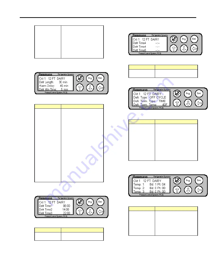
Figure 43- Circuit Configuration Screen 8
Table 22- Circuit Configuration Screen 8
Field
Explanation
Defr Length
Displays the amount of
time for a defrost. If there
is no termination or there
the controller does not get
the termination signal, this
is the maximum length of
time that the defrost will
last.
Alarm Delay
Displays the time delay for
an alarm if the controller is
in defrost.
Defr Min Time
Displays the minimum
time that the controller will
run a defrost for. A defrost
will run for this minimum
amount of time, even if a
termination signal occurs
before this period of time.
Figure 44- Circuit Configuration Screen 9
Table 23- Circuit Configuration Screen 9
Field
Explanation
Defr Time
1,2,3
Displays the time of the
defrost (24 hour format)
Figure 45- Circuit Configuration Screen 10
Table 24- Circuit Configuration Screen 10
Field
Explanation
Defr Time
4,5,6
Displays the time of the
defrost (24 hour format)
Figure 46- Circuit Configuration Screen 11
Table 25- Circuit Configuration Screen 11
Field
Explanation
Defr Type
Displays the type of
defrost (ELECTRIC, OFF
CYCLE or HOT GAS)
Defr Term
Type
Displays the type of
termination to use (TIME,
NONE, TEMPERATURE
or DIGITAL (Klixon))
Defr Term
Temp
Displays the termination
temperature for the circuit
Figure 47- Circuit Configuration Screen 12
Table 26- Circuit Configuration Screen 12
Field
Explanation
Temp 1,2,3
Displays input Board and
Point for the temperature
probes for this circuit.
Note that the assignment
of the board/point defines
whether a circuit is active.
Page 27


