Protocol
Control
System
Users
Manual
2/12/01
5. PCS Hardware
The following are components of the PCS system.
1) PCS Controller
2) PCS Expansion Board
3) PCS Pressure Transducer
4) PCS Temperature Probes
This document describes the elements of the PCS
components. The schematics included with each
Protocol Refrigeration System detail the connections that
are made to the components. Refer to the schematics for
connection details.
WARNING: The Controller and Expansion board use
low voltage (24 VAC) power. However, both units have
high voltage loads connected to them. Extreme caution
should be used when servicing these units. Failure to
observe caution could lead to injury or death.
5.1 PCS Controller
The PCS Controller is a microprocessor based system
that contains a built in display, keypad and I/O (relays
termperature inputs, pressure inputs and digital inputs).
It serves as the user interface and runs the algorithms that
control the protocol refrigeration system. Additional I/O
(relays, digital inputs and temperature inputs) can be
added using the PCS Expansion Board. The controller
contains all the I/O for all compressors in the Protocol
refrigeration system.
The temperature inputs must use the PCS temperature
sensors (described below) and the pressure inputs must
use the PCS pressure probes (described below).
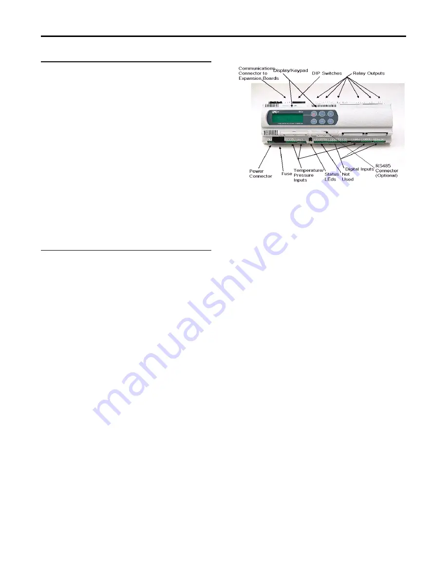
Figure 1 shows a picture of the PCS Controller and
identifies the different parts of the Controller.
Figure 1- PCS Controller
5.1.1 Input Power
The Controller uses 24 VAC (+/-15%, 50/60
Hz) (Class II) power at 50 VA.
5.1.2 Display Contrast Adjust
The contrast of the display can be adjusted by
pressing and holding the ENTER and ESC keys
together and pressing the UP ARROW key to
increase the contrast or the DOWN ARROW
key to decrease the contrast. Refer to
paragraph 7.1.1 for an explanation of how to
identify the keys.
5.1.3 Status LEDs
There are two LED’s on the Controller that
indicate power status. If the Yellow LED is ON
this indicates that the unit is getting power. If it
is OFF, there is either no power to the unit or
the fuse is blown. The Red LED indicates the
status of the Pressure probe power output
(Connector J2 , terminals GND and +VDC). If
the Red LED is ON, there is a fault in the probe
supply. Most likely, the pressure probe is bad
or there is a short in the cable.
5.1.4 DIP Switches
The DIP Switches on the controller should
always be in the down (OFF) position.
Page 8


