PDU8000 Modular Precision PDC V2.0
User Manual
A Appendix
Issue 03 (2018-01-25)
Huawei Proprietary and Confidential
Copyright © Huawei Technologies Co., Ltd.
145
A
Appendix
A.1 PDC Silk Screen Description
The silk screen content is in the format of route switch sequence number.
In the single-input scenario, the route number is omitted by default.
Table A-1
Symbols
Symbol
Name
QF
Circuit breaker
FU
Fuse
QFS
SPD circuit breaker
FS
SPD
The silk screen content is in the format of route switch sequence number. In the
single-input scenario, the route number is omitted by default. Symbols in the conceptual diagram are
described as follows:
QF: input switch when there is a single input.
QF1: first switch when there is a single input.
1QF: input circuit breaker for route I when there are two inputs.
2QF: input circuit breaker for route II when there are two inputs.
1QF1: first switch of route I when there are two inputs.
2QF1: first switch of route II when there are two inputs.
A.2 PDC Label Description
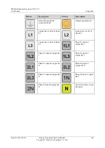
Table A-2
Label description
Picture
Description
Picture
Description
Located on the bottom or top
panel to indicate the cabinet
front
Located on the bottom
or top panel to indicate
the cabinet rear


