background image

PDU8000 Modular Precision PDC V2.0 
User Manual 

8 Maintenance Guide 


Issue 03 (2018-01-25) 

Huawei Proprietary and Confidential                                     

Copyright © Huawei Technologies Co., Ltd. 

143 


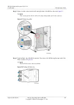
Figure 8-24


Adding an MCB 


Step 9


(Optional) If an MCB is incorrectly set, tap the MCB and then tap 

Modify

 to correct the 

phases and capacity.   

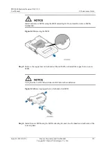
Figure 8-25


Modifying MCB settings 


Step 10


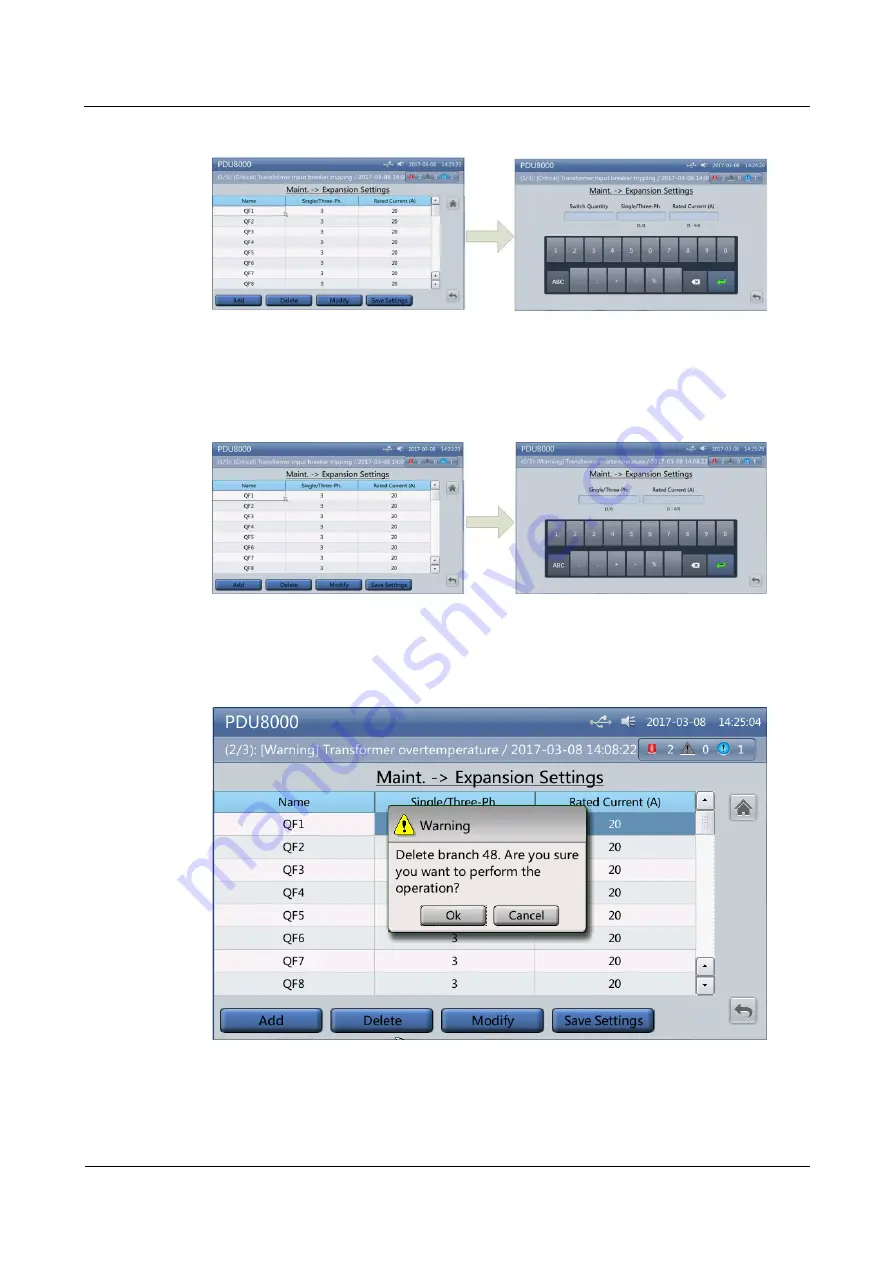
(Optional) If more MCBs are added than necessary, tap the extra MCB and then tap 

Delete

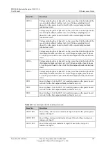
Figure 8-26


Deleting an MCB 


Step 11


After verifying that all added MCBs are correctly set, tap 

Save Settings

Step 12


The MDU automatically restarts, and the capacity expansion setting is complete. 

Содержание PDU8000 Series

Страница 1: ...PDU8000 Modular Precision PDC V2 0 User Manual Issue 03 Date 2018 01 25 HUAWEI TECHNOLOGIES CO LTD ...

Страница 2: ...e customer All or part of the products services and features described in this document may not be within the purchase scope or the usage scope Unless otherwise specified in the contract all statements information and recommendations in this document are provided AS IS without warranties guarantees or representations of any kind either express or implied The information in this document is subject...

Страница 3: ...ns and methods for installing commissioning and maintaining the modular precision power distribution cabinet PDC helping users to quickly understand methods for precision PDC operation and maintenance O M The figures provided in this manual are for reference only The actual product appearances and configurations prevail This document uses a 2000 mm high PDC as an example to describe how to install...

Страница 4: ... Manual About This Document Issue 03 2018 01 25 Huawei Proprietary and Confidential Copyright Huawei Technologies Co Ltd iii Product Model Figure 1 Product model Intended Audience This document is intended for Hardware installation engineers ...

Страница 5: ...tentially hazardous situation which if not avoided may result in minor or moderate injury Indicates a potentially hazardous situation which if not avoided could result in equipment damage data loss performance deterioration or unanticipated results NOTICE is used to address practices not related to personal injury Calls attention to important information best practices and tips NOTE is used to add...

Страница 6: ...Precision PDC V2 0 User Manual About This Document Issue 03 2018 01 25 Huawei Proprietary and Confidential Copyright Huawei Technologies Co Ltd v Issue 01 2017 05 28 This issue is used for first office application FOA ...

Страница 7: ... 6 3 2 Appearance 6 3 2 1 Appearance of the Modular Precision PDC with a Single Input 7 3 2 2 Appearance of the Modular Precision PDC with Dual Inputs 9 3 3 Features 12 3 4 Technical Specifications 13 3 5 Modules 15 3 5 1 Configuration Description 15 3 5 2 Power Distribution Module 17 3 5 3 Monitoring Module 19 3 6 Components 21 3 6 1 MDU 21 3 6 2 Monitoring Board 23 3 6 3 MCCB 24 3 6 4 MCB 25 3 6...

Страница 8: ...mmissioning 69 6 2 Power On Commissioning 70 7 MDU Commissioning Guide 73 7 1 UI Appearance 73 7 2 Menu Hierarchy 74 7 3 Common Functions 76 7 3 1 Historical Alarm 76 7 3 2 Branch Output 1 2 77 7 4 System Information 78 7 4 1 Running 78 7 4 1 1 Main Input 1 2 79 7 4 1 2 Branch Output 1 2 82 7 4 1 3 Input 1 2 Curve 83 7 4 1 4 Query Energy Yield 84 7 4 1 5 Mains 1 2 Temperature Curve 84 7 4 1 6 Bran...

Страница 9: ... Configurations 111 7 4 4 9 Fault Report 112 7 4 4 10 Uploading the CA Certificate and Certificate File 113 7 4 5 About 115 7 5 Operating Status 116 7 6 DIP Switches 116 8 Maintenance Guide 118 8 1 Routine Maintenance 118 8 2 Alarm Reference 120 8 3 Troubleshooting 124 8 4 Parts Replacement 125 8 4 1 Replacing an SPD Module 125 8 4 2 Replacing an Indicator 126 8 4 3 Replacing a Common MCB 128 8 4 ...

Страница 10: ...fore performing an operation ensure that the prerequisites are met Otherwise the expected result may not be achieved More seriously equipment damage and personal injury may occur Before using this document read through and keep in mind the safety precautions and the cautions and notes for operations Configuration parameters are essential to the reliable running of a system Improper modifications o...

Страница 11: ...nly supplemental to the local laws and regulations Personnel Requirements Personnel who plan to install operate and maintain Huawei equipment must be thoroughly trained understand all necessary safety precautions and master correct operation methods Only trained and qualified personnel are allowed to install operate and maintain the equipment Only personnel certified or authorized by Huawei are al...

Страница 12: ...a fire immediately leave the building or the equipment room and turn on the fire alarm bell or make an emergency call Never enter a building or equipment zone that is on fire Equipment Safety The device must be fixed securely on the floor or to other immovable objects such as walls or mounting racks before operation Do not block the ventilation vents while the device is operating Tighten the screw...

Страница 13: ...ontact between the core of the power cable and the conductor may generate electric arcs or sparks which may cause fire or injury to human eyes Before installing or removing a power cable turn off the power switch Before connecting a power cable verify that the label on the power cable is correct Fuse To ensure that the system runs safely if a fuse is to be replaced the new fuse must be of the same...

Страница 14: ...ng Signal Cables Signal cables must be bound separately from strong current cables and high voltage cables Laying Out Power Cables When the temperature is very low violent impact or vibration may damage the power cable sheathing To ensure safety comply with the following requirements Power cables should be laid out or installed only when the temperature is higher than 0 C Store power cables for at...

Страница 15: ...or power distribution and electric parameter measurement It provides precision electricity management for critical loads in building or container data centers Figure 3 1 Positioning of the modular precision PDC 3 2 Appearance The PDU8000 modular precision PDC is equipped with a smart precision monitoring system It provides comprehensive functions for power distribution electrical parameter measure...

Страница 16: ...ular Precision PDC with a Single Input This section uses the full configuration with three output modules as an example Figure 3 2 Appearance 2000 mm high 1 Indicators 2 MCCB input circuit breaker 3 SPD and SPD circuit breaker 4 Monitoring board 1 5 Monitoring board 4 6 Monitoring board 2 7 Monitoring board 5 8 MCB output circuit breaker 9 Monitoring board 3 10 Monitoring board 6 ...

Страница 17: ...ential Copyright Huawei Technologies Co Ltd 8 Figure 3 3 Appearance 2200 mm high 1 Indicators 2 MCCB input circuit breaker 3 SPD and SPD circuit breaker 4 Monitoring board 1 5 Monitoring board 4 6 Monitoring board 2 7 Monitoring board 5 8 MCB output circuit breaker 9 Monitoring board 3 10 Monitoring board 6 ...

Страница 18: ... mm high 1 Indicators 2 MCCB input circuit breaker 3 SPD and SPD circuit breaker 4 Monitoring board 1 5 Monitoring board 4 6 Monitoring board 2 7 Monitoring board 5 8 MCB output circuit breaker 9 Monitoring board 3 10 Monitoring board 6 3 2 2 Appearance of the Modular Precision PDC with Dual Inputs This section uses the full configuration with three output modules as an example ...

Страница 19: ...tors of route I 2 Indicators of route II 3 Input circuit breaker of route I 4 Input circuit breaker of route II 5 SPD and SPD circuit breaker of route I 6 SPD and SPD circuit breaker of route II 7 Monitoring board 1 8 Monitoring board 4 9 Output circuit breaker of route I 10 Output circuit breaker of route II 11 Monitoring board 2 12 Monitoring board 5 13 Monitoring board 3 14 Monitoring board 6 ...

Страница 20: ...tors of route I 2 Indicators of route II 3 Input circuit breaker of route I 4 Input circuit breaker of route II 5 SPD and SPD circuit breaker of route I 6 SPD and SPD circuit breaker of route II 7 Monitoring board 1 8 Monitoring board 4 9 Output circuit breaker of route I 10 Output circuit breaker of route II 11 Monitoring board 2 12 Monitoring board 5 13 Monitoring board 3 14 Monitoring board 6 ...

Страница 21: ...D circuit breaker of route I 6 SPD and SPD circuit breaker of route II 7 Monitoring board 1 8 Monitoring board 4 9 Output circuit breaker of route I 10 Output circuit breaker of route II 11 Monitoring board 2 12 Monitoring board 5 13 Monitoring board 3 14 Monitoring board 6 3 3 Features Table 3 1 Features Feature Description High efficiency and low cost Highly integrated normalized designs for str...

Страница 22: ...ring Strong networking capability for teleindication telemetry telecontrol and teleadjusting Real time monitoring and alarm reporting Optional Temperature monitoring Capacity expansion Optional Capacity expansion for hot swap circuit breakers with power on Fire linkage Optional The non fire extinguishing power supply is cut off by using 24 V DC before extinguishant is released 3 4 Technical Specif...

Страница 23: ...the top or bottom Environmental friendliness RoHS REACH Overvoltage level II Operating temperature 5 C to 40 C Relative humidity 5 95 non condensing Altitude 2000 m If the altitude exceeds 2000 m the device is derated according to GB T3859 2 93 Table 3 3 Safety and EMC Item Specifications Safety CCC CE TL N A EMC Conducted emission CE EN55022 CLASS A Radiated emission RE EN55022 CLASS A Voltage fl...

Страница 24: ... of the cabinet power distribution subracks MCCBs MCBs cables wiring terminals fuse suite indicators and transformers Determine the specifications and quantity of MCCBs and MCBs to be configured based on the requirement Number of inputs single or dual inputs Input capacity 630 A 400 A 250 A 160 A Number and capacity of output MCBs determined based on customer requirements Figure 3 8 Cabinet config...

Страница 25: ...Huawei Proprietary and Confidential Copyright Huawei Technologies Co Ltd 16 Figure 3 9 Cabinet configuration 2200 mm high 1 Top frame 5 U high 2 Indicator module 1 U high 3 Input module 10 U high 4 Output module 1 10 U high 5 Output module 2 10 U high 6 Output module 3 10 U high ...

Страница 26: ... 1 Indicator module 1 U high 2 Input module 10 U high 3 Output module 1 10 U high 4 Output module 2 10 U high 5 Output module 3 10 U high 3 5 2 Power Distribution Module The power distribution module is used for receiving and distributing power and consists of the MCCB input module MCB output module and a power distribution bus MCCB input modules are classified into single route and dual route one...

Страница 27: ...ecision PDC V2 0 User Manual 3 Overview Issue 03 2018 01 25 Huawei Proprietary and Confidential Copyright Huawei Technologies Co Ltd 18 Figure 3 11 Single route MCCB input module Figure 3 12 Dual route MCCB input module ...

Страница 28: ...tion Module Function MCCB input module Provides overload and short circuit protection Collects currents Provides level C surge protection MCB output module Distributes power and provides overload and short circuit protection 3 5 3 Monitoring Module The monitoring module is used to display and monitor electrical parameters It consists of the Monitor Display Unit MDU monitoring board and signal cabl...

Страница 29: ...on Module Function MDU Provides menus for setting PDC parameters and viewing the PDC operating status and alarms Upgrading software Optional Detects temperatures Monitoring board Collects parameters such as circuit breaker status and voltages and currents of the main route and branches Calculates the main route electric energy frequency voltage current active power and reactive power based on the ...

Страница 30: ...atus Indicator Status Description Red A critical alarm has been generated and the buzzer buzzes Yellow A major alarm has been generated and the buzzer buzzes at an interval of 0 5s Green A warning has been generated or the system is running properly Off The MDU powers off Blinking The indicator blinks at super short intervals for 0 5s blinking at 10 Hz on for 0 05s and then off for 0 05s and then ...

Страница 31: ...odbus TCP is used 3 CAN Internal communications and power supply port for the MDU LCD 4 RS485_1 Northbound port that connects to the management system when Modbus RTU is used 5 USB Host USB host port 6 RST MDU reset button 7 SD Installing an SD card 8 SW1 4 DIP switch By setting DIP switch toggles in different combinations you can perform operations such clearing historical alarms clearing logs an...

Страница 32: ...er input 7 inch TFT LCD display module Board ambient temperature 20 C to 70 C Operating humidity 5 95 RH 3 6 2 Monitoring Board There are two types of monitoring boards with the same appearance The monitoring board with the BOM number 02311GDJ can convert AC into 12 V DC and can be installed in all output modules of a cabinet The monitoring board with the BOM number 02311GDJ 001 can convert 15 V D...

Страница 33: ...erates a monitoring board communication failure alarm Blinking red Power supply to the monitoring board is faulty or there is a surge current impact alarm Off The monitoring board is not working Table 3 10 Functions and specifications of the monitoring board Item Remarks Function Measures parameters such as the voltages and currents of the mains and branch circuits Provides the communication funct...

Страница 34: ... Function Connects and disconnects the circuit under normal working status Provides overload and short circuit protection Provides the I1 knob for setting the thermal tripping value Specifications Rated insulation voltage 800 V AC Rated frequency 50 Hz 60 Hz Operating temperature 5 C to 40 C 3 6 4 MCB MCBs are classified into 1P and 3P MCBs Figure 3 20 Appearance of a 1P MCB Figure 3 21 Appearance...

Страница 35: ...oad and short circuit protection Specifications Rated voltage IEC 1P 250 V AC IEC 3P 440 V AC UL489 1P 3P 277 480 V AC Rated insulation voltage 440 V AC Rated frequency 50 Hz 60 Hz Operating temperature 25 C to 55 C Rated short circuit resistance IEC EN 60898 Icn 6 kA Rated limiting short circuit breaking capacity 6 kA Rated surge voltage tolerance 1 2 50 4 kV Pyromagnetic tripping B 3 In Im 5 In ...

Страница 36: ...7 Table 3 13 SPD functional parameters Item Description Function Provides lightening and transient voltage surge protection Specifications Operating temperature 40 C to 70 C Operating humidity 5 95 RH Nominal discharge current In 8 20 µs 20 kA Maximum discharge current Imax 8 20 µs 40 kA Voltage protection level Up 20 kA 8 20 μs 1 8 kV L N 1 0 kV N PE ...

Страница 37: ...h caution to avoid bumping or toppling To avoid damaging the equipment exercise caution when removing the packing materials Step 1 Check whether the tiltwatch indicator on the carton has turned red If yes record the information and contact the equipment carrier and the local Huawei office immediately Step 2 Visually inspect the equipment appearance to check whether the equipment is paint peeling m...

Страница 38: ...yright Huawei Technologies Co Ltd 29 Unpacking Step 1 Move the PDC to the specified installation position using a forklift Step 2 Cut off and remove the binding straps Figure 4 1 Removing the binding straps Step 3 Remove the packing materials and foam Step 4 Remove the plastic bag take out the fitting box and put it away End ...

Страница 39: ...ting requirements see the Schematic Diagram delivered with the product for details Temperature 5 C to 40 C Relative humidity 5 95 RH non condensing Altitude 2000 m derated when the altitude exceeds 2000 m For the derating details contact Huawei technical support Huawei will not be liable for any consequences caused if the installation environment does not meet the requirements 5 2 Installation Pre...

Страница 40: ...ent from the website PDU8000 Modbus Protocol for External Systems Used to access a third party network management system Download this document from the website 5 2 2 Obtaining Tools and Materials The construction team needs to prepare the tools meters and basic materials required for hardware installation Table 5 2 Tools and materials Categor y Tools and Materials Tighteni ng tools M5 M6 M8 Phill...

Страница 41: ...pyright Huawei Technologies Co Ltd 32 Categor y Tools and Materials Crimping tool Wire stripper Electric hydraulic pliers Cable cutter Power tools Hammer drill Heat gun Vacuum cleaner Instrume nts Multimeter Electroprobe Network cable tester Auxiliar y tools Right angle Measuring tape 5 m Level Claw hammer Scissors Box cutter ...

Страница 42: ...uawei Technologies Co Ltd 33 Categor y Tools and Materials Hacksaw Step ladder 2 m Hammer drill bits Φ16 Rubber mallet Pallet truck Accessor ies Cons umables cable tie Polyvinyl chloride PVC insulation tape Marker ESD gloves Protective gloves Safety helmet Safety goggles ESD wrist strap Insulated gloves Protective shoes Firestop putty ...

Страница 43: ...obtained work permits before they begin to install and commission equipment The number of construction personnel depends on the project progress and the installation environment Construction personnel have read through the safety precautions and related product documents before they begin work 5 3 Installing the PDC Prerequisites The installation environment has been checked with expected results ...

Страница 44: ...t to prevent toppling and bumping Procedure Step 1 Remove the two L shaped brackets between the front and rear door sills of the PDC and the pallet as shown by 1 and 2 in Figure 5 1 Figure 5 1 Removing L shaped brackets Step 2 Use diagonal pliers to cut off the binding straps securing the unloading ramps and take out the unloading ramps on both sides as shown by 3 in Figure 5 1 Step 3 Clip the unl...

Страница 45: ... 4 Adjust the PDC leveling feet using a wrench to ensure that all castors touch the ground Step 5 Arrange four persons to push the PDC off the wooden pallet to the ground with caution End 5 3 2 Installing the PDC on a Concrete Floor Procedure Step 1 Mark the positions for installing expansion bolts based on the marking off template Each PDC is delivered with one marking off template of the corresp...

Страница 46: ... x 1100 mm 2000 mm x 600 mm x 1100 mm Figure 5 4 Marking off template PDC dimensions 2000 mm x 600 mm x 1200 mm Step 2 Drill holes in the marked positions using a hammer drill Step 3 Slightly tighten expansion bolts to prevent the expansion sleeves from fluttering Step 4 Knock the expansion bolts vertically into mounting holes until the flat washers are flush with the floor Step 5 Remove the bolt ...

Страница 47: ...yright Huawei Technologies Co Ltd 38 Figure 5 5 Installing expansion sleeves 1 M12 bolt 2 Spring washer 3 Flat washer 4 Expansion sleeve 5 Concrete floor Step 6 Align the PDC mounting holes with the expansion bolt holes Step 7 Adjust the anchor bolts of the PDC using an adjustable wrench until the leveling feet touch the floor ...

Страница 48: ...ch a leveling foot clockwise to elevate a cabinet foot or wrench a leveling foot anticlockwise to lower it The cabinet feet can be adjusted within a range of 0 8 mm To prevent cabinet tilting adjust all the feet at the four corners instead of one foot Do not remove leveling feet because this work brings you only a great deal of reworking Step 8 Level the PDC using a level and an adjustable wrench ...

Страница 49: ...d Confidential Copyright Huawei Technologies Co Ltd 40 Figure 5 7 Leveling the PDC 1 Level Step 9 Partially tighten the expansion bolt Step 10 Optional Combine cabinets Remove the cabinet connecting plates from the rack and then secure the connecting plates in the connection positions on the door using screws ...

Страница 50: ... 5 Installation Guide Issue 03 2018 01 25 Huawei Proprietary and Confidential Copyright Huawei Technologies Co Ltd 41 Figure 5 8 Combining PDCs Step 11 Use a socket wrench to tighten the bolts in diagonal order Figure 5 9 Tighten the PDC bolts End ...

Страница 51: ...ground and the ESD floor Procedure Step 1 Lower the leveling feet of the PDC using an adjustable wrench until all castors are off the ground and the cabinet is level Step 2 Lift the PDC onto the support and align the mounting holes in the PDC with those in the support Step 3 Level the PDC by adjusting the leveling feet Figure 5 10 Leveling PDC 1 Leveling foot 2 Level Step 4 Insert four M12 bolts i...

Страница 52: ...PDC cannot be secured using the mounting holes secure the PDC using the mechanical part shown in the following figure Figure 5 12 Securing the cabinet using mechanical parts Step 5 Optional Combine cabinets Remove the cabinet connecting plates from the rack and then secure the connecting plates in the connection positions on the door using screws Figure 5 13 Combining PDCs Step 6 Use a socket wren...

Страница 53: ...hown in Figure 5 14 and Figure 5 15 4 Each output power cable bundle can contain 5 10 cables If too many cables are bound together the cables may overheat due to poor heat dissipation 5 Extra cables are coiled neatly and easy to find 6 Cables on the surface of a large cable bundle are neatly organized without unnecessary crossover 7 Cables are arranged in distinct layers and crossovers are avoided...

Страница 54: ...Bending Table 5 5 Cable bending rules No Cable Bending Rule 1 Cables are not overly bent as over bending may damage the cable cores 2 Unless otherwise stipulated the bending radius should be 10 times greater than the cable diameter if the installation space is sufficient 3 Cables are not tied where they bend as shown in Figure 5 17 4 Cables must be a little longer than the exact cable route length...

Страница 55: ...xtra length for easy plug and unplug Figure 5 19 Stroking cables Cable Layout Table 5 6 Cable layout rules No Cable Layout Rule 1 The armoring layers of armored cables are grounded 2 The PDC ground cable is secured to the equipment room ground bar The resistance between the PDC ground cable and the equipment room ground bar is less than 0 1 ohm 3 Cables are securely connected in the correct phase ...

Страница 56: ...r each circuit breaker Cables are converged at the beam and bound in groups by cable ties 5 4 2 Power Cable Specifications YJV 5 core cables are recommended When the ambient temperature is 40 C the conductor working temperature cannot exceed 90 C For the installation torque for power connection of involved electrical parts see the specifications of the electrical parts If the torque is not specifi...

Страница 57: ...commended Torque N m 10 I 40 6 Cord end terminal crimping screw specification M4 1 2 40 I 63 10 Cord end terminal crimping screw specification M4 1 2 AC output N PE 10 2 5 OT M6 4 5 10 I 40 6 OT M6 4 5 40 I 63 10 OT M6 4 5 5 4 3 Preparing Terminals Figure 5 20 Figure 5 21 and Figure 5 22 respectively show how to prepare DT OT and cord end terminals Figure 5 20 Preparing a DT terminal 1 Cable 2 Hea...

Страница 58: ...1 Cable 2 Heat shrink tubing 3 OT terminal 4 Electric hydraulic pliers 5 Heat gun Figure 5 22 Preparing a cord end terminal 1 Cable 2 Cord end terminal 3 Crimping tool There are two types of RJ45 connectors including 568A and 568B as shown in Figure 5 23 and Figure 5 24 Using 568A as an example The RJ45 connector can be connected in the 4 wire or 2 wire methods as shown in Figure 5 25 and Figure 5...

Страница 59: ...ion PDC V2 0 User Manual 5 Installation Guide Issue 03 2018 01 25 Huawei Proprietary and Confidential Copyright Huawei Technologies Co Ltd 50 Figure 5 23 568A RJ45 connector Figure 5 24 568B RJ45 connector Figure 5 25 4 wire ...

Страница 60: ...uide Issue 03 2018 01 25 Huawei Proprietary and Confidential Copyright Huawei Technologies Co Ltd 51 Figure 5 26 2 wire 5 4 4 Connecting Cables Cable Holes Figure 5 27 Cable holes at the top 1 Monitoring cable hole 2 Power cable inlet hole 3 Power cable outlet hole ...

Страница 61: ... scenario Connection Method Keep away from cabinets when preparing cables to prevent cable scraps from entering the cabinets Cable scraps may cause ignition during power on and result in personal injury and device damage After installing cables clean the cabinet top bottom copper bar wiring positions and other positions Ensure that there is no dust or scraps inside and around cabinets Prepare term...

Страница 62: ... situation The figure is for reference only Step 4 Connect the cable with a crimped terminal to the corresponding copper bar Step 5 Clean foreign matter inside the cabinet End 5 4 4 1 Top Cable Routing The following procedure applies to a dual input PDC Procedure Step 1 Remove the rodent proof meshes at the top and put them aside Figure 5 30 Removing rodent proof meshes at the top Step 2 Remove th...

Страница 63: ... and Confidential Copyright Huawei Technologies Co Ltd 54 Figure 5 31 Removing the transparent covers of the N bar and input copper bar Step 3 Connect the equipotential ground cables for the cabinet Figure 5 32 Connecting the equipotential ground cables for the cabinet Step 4 Connect the input power cables ...

Страница 64: ... Co Ltd 55 In single input scenarios connect the input N cable to 1N When connecting the input power cables verify that the screw assemblies face the same direction and that the nuts face the cabinet rear door Connect the three phase cables N cable and PE cable in sequence Figure 5 33 Connecting input power cables Step 5 Connect the output power cables ...

Страница 65: ...Manual 5 Installation Guide Issue 03 2018 01 25 Huawei Proprietary and Confidential Copyright Huawei Technologies Co Ltd 56 Figure 5 34 Connecting output power cables Step 6 The following figure shows the overall effect after cable connection ...

Страница 66: ...al 5 Installation Guide Issue 03 2018 01 25 Huawei Proprietary and Confidential Copyright Huawei Technologies Co Ltd 57 Figure 5 35 Overall cable connection effect Step 7 Connect the PDC monitoring cable to the RS485_1 or FE port on the MDU side ...

Страница 67: ...ls of the fire control cable to the 24VDC and 24VDC wiring terminals at the rear right of the cabinet respectively Dual input PDC Connect the positive and negative terminals of the fire control cable to the 24VDC and 24VDC wiring terminals at the rear left or rear right of the cabinet respectively Scenario 2 dual input PDC either of the two pairs of fire extinguishing input cables can control all ...

Страница 68: ...V DC cables routed into the PDC should be shielded cables 2 Ensure that the polarities of 24 V DC cables routed into the PDC are correct Figure 5 37 Connecting the fire linkage cables scenario 1 Figure 5 38 Connecting the fire linkage cables scenario 2 Step 9 Cut cable inlet and outlet holes in the rodent proof meshes based on the number and size of cables to be routed ...

Страница 69: ...ll the transparent covers of the input copper bar and N bar Step 12 Seal the gap between cables and the cabinet using flake sealing putty Remove the paper protective film from the sealing putty and use the aluminum foil film together with the sealing putty Figure 5 40 Fill the holes with flake sealing putty End 5 4 4 2 Bottom Cable Routing The following procedure applies to a single input PDC Proc...

Страница 70: ...yright Huawei Technologies Co Ltd 61 Figure 5 41 Removing rodent proof meshes at the bottom Step 2 Remove the transparent covers of the N bar and input copper bar and put the covers aside Figure 5 42 Removing the transparent covers of the N bar and input copper bar Step 3 Connect the equipotential ground cables for the cabinet ...

Страница 71: ...User Manual 5 Installation Guide Issue 03 2018 01 25 Huawei Proprietary and Confidential Copyright Huawei Technologies Co Ltd 62 Figure 5 43 Connecting the equipotential ground cables for the cabinet Step 4 Connect the input power cables ...

Страница 72: ... Co Ltd 63 In single input scenarios connect the input N cable to 1N When connecting the input power cables verify that the screw assemblies face the same direction and that the nuts face the cabinet rear door Connect the three phase cables N cable and PE cable in sequence Figure 5 44 Connecting input power cables Step 5 Connect the output power cables ...

Страница 73: ...Manual 5 Installation Guide Issue 03 2018 01 25 Huawei Proprietary and Confidential Copyright Huawei Technologies Co Ltd 64 Figure 5 45 Connecting output power cables Step 6 The following figure shows the overall effect after cable connection ...

Страница 74: ...al 5 Installation Guide Issue 03 2018 01 25 Huawei Proprietary and Confidential Copyright Huawei Technologies Co Ltd 65 Figure 5 46 Overall cable connection effect Step 7 Connect the PDC monitoring cable to the RS485_1 or FE port on the MDU side ...

Страница 75: ...ls of the fire control cable to the 24VDC and 24VDC wiring terminals at the rear right of the cabinet respectively Dual input PDC Connect the positive and negative terminals of the fire control cable to the 24VDC and 24VDC wiring terminals at the rear left or rear right of the cabinet respectively Scenario 2 dual input PDC either of the two pairs of fire extinguishing input cables can control all ...

Страница 76: ...V DC cables routed into the PDC should be shielded cables 2 Ensure that the polarities of 24 V DC cables routed into the PDC are correct Figure 5 48 Connecting the fire linkage cables scenario 1 Figure 5 49 Connecting the fire linkage cables scenario 2 Step 9 Cut cable inlet and outlet holes in the rodent proof meshes based on the number and size of cables to be routed ...

Страница 77: ... the rodent proof meshes Step 10 Reinstall the rodent proof meshes Step 11 Reinstall the transparent covers of the input copper bar and N bar Step 12 Seal the gap between cables and the cabinet using flake sealing putty Remove the paper protective film from the sealing putty and use the aluminum foil film together with the sealing putty Figure 5 51 Fill the holes with flake sealing putty End ...

Страница 78: ... 2 The paint on the cabinet exterior is intact Yes No 3 The cabinet door and lock work properly Yes No 4 All labels are correct clear and complete Yes No 5 The surrounding area of the cabinet contains no waste tape cable ties paper or packing materials Yes No Table 6 2 Electrical connection checklist No Check Item Result 1 All cables are connected properly Yes No 2 The ground cable is connected pr...

Страница 79: ...equirements for routing power cables and signal cables and complies with the cable routing plan Yes No 6 2 Power On Commissioning Context The power on commissioning process requires at least two qualified electricians one responsible for operations and the other for monitoring Cautions and warnings must be properly placed onsite Users are categorized as admin and operator Admin users have more rig...

Страница 80: ...gohm using a multimeter 3 After checking turn off all the circuit breakers Step 3 Switch on the SPD circuit breaker If the indicator of an SPD module is green the SPD module is running properly If an indicator is red the corresponding SPD module has failed and must be promptly replaced Figure 6 2 Switching on the SPD circuit breaker Step 4 Switch on the input power circuit breaker to power on the ...

Страница 81: ...igures are for reference only The actual parameter values prevail Step 6 After the quick settings are complete if the monitoring page displays alarms clear the alarms For system security purposes change the preset password upon first login Step 7 Turn on the input switches on the front panel of the PDC Step 8 Switch on the output circuit breakers except reserved circuit breakers in the PDC in sequ...

Страница 82: ...screen consists of a status bar an alarm bar a menu bar and an information area Figure 7 1 Home screen Table 7 1 Function Description No Area Function Description 1 Status bar The status bar displays the product model Universal Serial Bus USB flash drive buzzer status and current date and time 2 Alarm bar The alarm bar displays active alarms in a scrolling manner and the numbers of active critical...

Страница 83: ...erating Status 4 Information area Table 7 2 lists the functions of common buttons in the information window Table 7 2 Functions of common buttons in the information window Button Function Description Returns to the upper level menu Goes to the previous screen Goes to the next screen Returns to the main menu screen Logs out 7 2 Menu Hierarchy This section uses a cabinet with dual three phase inputs...

Страница 84: ...PDU8000 Modular Precision PDC V2 0 User Manual 7 MDU Commissioning Guide Issue 03 2018 01 25 Huawei Proprietary and Confidential Copyright Huawei Technologies Co Ltd 75 Figure 7 2 Menu hierarchy ...

Страница 85: ...de Issue 03 2018 01 25 Huawei Proprietary and Confidential Copyright Huawei Technologies Co Ltd 76 7 3 Common Functions Figure 7 3 Common Functions 7 3 1 Historical Alarm On the Common Functions screen tap Historical Alarm to access the screen Figure 7 4 Historical Alarm ...

Страница 86: ...al Copyright Huawei Technologies Co Ltd 77 7 3 2 Branch Output 1 2 On the Common Functions screen tap Branch Output 1 to view the detailed parameters of each circuit breaker of Branch Output 1 For the information about the Branch Output 2 screen refer to Branch Output 1 Figure 7 5 Branch Output 1 1 Figure 7 6 Branch Output 1 2 ...

Страница 87: ...ight Huawei Technologies Co Ltd 78 7 4 System Information On this screen you can query the operating status alarm status and software version of the system You can also set and maintain model information for the system Figure 7 7 System Info 7 4 1 Running On the System Info screen tap Running to access the screen Figure 7 8 Running 1 ...

Страница 88: ...2018 01 25 Huawei Proprietary and Confidential Copyright Huawei Technologies Co Ltd 79 Figure 7 9 Running 2 Figure 7 10 Running 3 7 4 1 1 Main Input 1 2 On the Running screen tap Main Input 1 to access the screen For the information about the Main Input 2 screen refer to Main Input 1 ...

Страница 89: ...dular Precision PDC V2 0 User Manual 7 MDU Commissioning Guide Issue 03 2018 01 25 Huawei Proprietary and Confidential Copyright Huawei Technologies Co Ltd 80 Figure 7 11 Main Input 1 1 Figure 7 12 Main Input 1 2 ...

Страница 90: ... Figure 7 13 Main Input 1 3 Figure 7 14 Main Input 1 4 Power factor Indicates the ratio of the input active power to input apparent power Phase voltage V Phase current A Frequency Hz Indicates the mains input phase voltage mains input phase current and mains input frequency Load ratio Indicates the load ratio of each phase that is ratio of actual power to rated power ...

Страница 91: ...lectricity energy of all phases of the mains input Tot apparent pwr kVA Indicates the sum of apparent power of all phases of the mains input Tot reactive pwr kVAR Indicates the sum of reactive power of all phases of the mains input Temp C Indicates the mains temperature 7 4 1 2 Branch Output 1 2 On the Running screen tap Branch Output 1 to view the detailed parameters of Branch Output 1 For the in...

Страница 92: ...roprietary and Confidential Copyright Huawei Technologies Co Ltd 83 Figure 7 16 Branch Output 1 2 7 4 1 3 Input 1 2 Curve On the Running screen tap Input 1 Curve to view the load ratio of the main input For the information about the Input 2 Curve screen refer to Input 1 Curve Figure 7 17 Input 1 Curve ...

Страница 93: ...rgy Yield On the Running screen tap Query Energy Yield to enter the screen Then you can query the total energy yield in a time period after setting the start and end time Figure 7 18 Query Energy Yield 7 4 1 5 Mains 1 2 Temperature Curve On the Running screen tap Mains 1 Temp Curve to access the screen For the information about the Mains 2 Temp Curve screen refer to Mains 1 Temp Curve ...

Страница 94: ...s Co Ltd 85 Figure 7 19 Mains 1 Temp Curve 7 4 1 6 Branch 1 2 Temperature Curve On the Running screen tap Br 1 Temp Curve to access the screen For the information about the Br 2 Temp Curve screen refer to Br 1 Temp Curve Figure 7 20 Br 1 Temp Curve 7 4 1 7 Branch 1 2 Subrack Temperature Curve On the Running screen tap Br1 Sub Temp Curve to access the screen ...

Страница 95: ...gies Co Ltd 86 For the information about the Br2 Sub Temp Curve screen refer to Br1 Sub Temp Curve Figure 7 21 Br1 Sub Temp Curve 7 4 1 8 Branch 1 2 Terminal Temperature Curve On the Running screen tap Br1 Ter Temp Curve to access the screen For the information about the Br2 Ter Temp Curve screen refer to Br1 Ter Temp Curve Figure 7 22 Br1 Ter Temp Curve ...

Страница 96: ... 2018 01 25 Huawei Proprietary and Confidential Copyright Huawei Technologies Co Ltd 87 7 4 2 Alarms On the System Info screen tap Alarms to access the screen Figure 7 23 Alarms 7 4 2 1 Active Alarm On the Alarms screen tap Active Alarm to access the screen Figure 7 24 Active Alarm ...

Страница 97: ...screen tap Historical Alarm to access the screen Figure 7 25 Historical Alarm 7 4 2 3 Buzzer Off Two buzzer control items are available that is Buzzer On and Buzzer Off If the buzzer of the system is muted Buzzer On is displayed on the operation screen If the buzzer of the system is enabled Buzzer Off is displayed on the operation screen On the Alarms screen tap Buzzer Off and tap OK on the displa...

Страница 98: ...ame way If you enable the buzzer the buzzer buzzes when a critical alarm minor alarm or warning is generated If you mute the buzzer the buzzer does not buzz no matter what alarms are generated 7 4 3 Settings On the System Info screen tap Settings to access the screen If you have not logged in the system displays the login dialog box Enter the initial user name and password and tap to log in to the...

Страница 99: ...ies Co Ltd 90 The default user name is operator and the initial password is 000001 If you enter incorrect passwords for three consecutive times your account will be locked for 5 minutes If you do not operate the screen for 3 minutes the System Info screen is displayed and the system performs a forcible logout Figure 7 27 Settings 1 Figure 7 28 Settings 2 ...

Страница 100: ...25 Huawei Proprietary and Confidential Copyright Huawei Technologies Co Ltd 91 7 4 3 1 Common Settings On the Settings screen tap Common to access the screen Figure 7 29 Common 1 Figure 7 30 Common 2 7 4 3 2 Communication Settings On the Settings screen tap Communication to access the screen ...

Страница 101: ...f the MDU is directly connected to a computer the IP address can only be allocated manually The IP addresses of the MDU and computer must be in the same network segment and must be different If the MDU is connected to a computer through a LAN switch or router with the DHCP function the IP address can be allocated manually or automatically Manual The IP addresses of the MDU and computer must be in ...

Страница 102: ... is unique on the network segment Otherwise the LCD cannot work properly Subnet mask Set a subnet mask for the Ethernet The value ranges from 0 0 0 0 to 255 255 255 255 The default value is 255 255 255 0 Gateway Set an Ethernet gateway The value ranges from 0 0 0 0 to 255 255 255 255 The default value is 192 168 0 1 Serial port baud rate Set the serial port communications rate The value options in...

Страница 103: ...logies Co Ltd 94 Figure 7 33 System Param 1 Figure 7 34 System Param 2 Rated frequency Hz Specifies the rated frequency of the PDU8000 The value ranges from 45 to 65 Rated line voltage V Specifies the rated voltage of the PDU8000 The value ranges from 100 to 480 Rated current A Specifies the rated current of the PDU8000 The value is 160 250 400 and 650 ...

Страница 104: ...alue ranges from 150 to 500 x harmonic frequency The value ranges from 2 to 63 y harmonic frequency The value ranges from 2 to 63 z harmonic frequency The value ranges from 2 to 63 Package integrity protection Can be set to Disable or Enable 7 4 3 4 Branch Parameter Settings On the Settings screen tap Branch Param to access the screen Tap Set Branch 1 Alias or Set Branch 2 Alias to set circuit bre...

Страница 105: ...Confidential Copyright Huawei Technologies Co Ltd 96 Specifies the rated current of each branch The value is 10 16 25 32 40 50 and 63 7 4 3 5 Threshold Settings On the Settings screen tap Threshold to access the screen Figure 7 36 Threshold 1 Figure 7 37 Threshold 2 Open phase voltage V The value ranges from 0 to 60 ...

Страница 106: ...value ranges from 1 to 10 Overload Specifies the overload alarm threshold in relative to the rated load The value ranges from 100 to 120 Overload ack time s Specifies the duration for confirming an overload alarm The value ranges from 1 to 10 Overfrequency Hz Specifies the overfrequency alarm threshold in relative to the rated frequency The value ranges from 1 to 10 Overfrequency ack time s Specif...

Страница 107: ...lar Precision PDC V2 0 User Manual 7 MDU Commissioning Guide Issue 03 2018 01 25 Huawei Proprietary and Confidential Copyright Huawei Technologies Co Ltd 98 Figure 7 38 Setting Wizard 1 Figure 7 39 Setting Wizard 2 ...

Страница 108: ...issioning Guide Issue 03 2018 01 25 Huawei Proprietary and Confidential Copyright Huawei Technologies Co Ltd 99 Figure 7 40 Setting Wizard 3 Figure 7 41 Setting Wizard 4 7 4 3 7 Alarm Mask Setting On the Settings screen tap Alarm Masking to access the screen ...

Страница 109: ...MDU Commissioning Guide Issue 03 2018 01 25 Huawei Proprietary and Confidential Copyright Huawei Technologies Co Ltd 100 Figure 7 42 Alarm Masking 1 Figure 7 43 Alarm Masking 2 7 4 4 Maintenance On the System Info screen tap Maint to access the screen ...

Страница 110: ...000 Modular Precision PDC V2 0 User Manual 7 MDU Commissioning Guide Issue 03 2018 01 25 Huawei Proprietary and Confidential Copyright Huawei Technologies Co Ltd 101 Figure 7 44 Maint 1 Figure 7 45 Maint 2 ...

Страница 111: ... Technologies Co Ltd 102 Figure 7 46 Maint 3 7 4 4 1 Upgrading Software Prerequisites To upgrade the software perform the following steps Procedure Step 1 Connect a USB flash drive to the USB Host port The message A new USB device is found is displayed Step 2 Log in to the Maint screen as user admin and tap Upgrade Software to access the screen ...

Страница 112: ... Copyright Huawei Technologies Co Ltd 103 Figure 7 47 Upgrade Software 1 Step 3 Tap Upload on the displayed screen select the upgrade software package and tap Next Figure 7 48 Upgrade Software 2 Tap the folder to view its subfolders Step 4 On the displayed screen wait until the software package is automatically copied and parsed ...

Страница 113: ... 104 Figure 7 49 Upgrade Software 3 Step 5 After the software package is copied and parsed the software activation screen is displayed again Select the software package and tap Details to activate the software package Figure 7 50 Upgrade Software 4 Step 6 Tap Activate to activate the software After the software is activated the MDU restarts to complete the upgrade ...

Страница 114: ...he monitoring board is not displayed after the MDU is restarted In this case tap Upgrade Software to continue the upgrading process If the PDC is powered off when the software for the MDU is being upgraded perform the upgrading again after the MDU is restarted After the software is upgraded the MDU parameters remain unchanged and do not need to be reset End 7 4 4 2 Loading Configurations Context T...

Страница 115: ...al Copyright Huawei Technologies Co Ltd 106 Figure 7 52 Inserting the USB flash drive Step 2 On the Maint screen tap Load Config to access the screen Step 3 Select the file to be loaded and tap Next Figure 7 53 Loading configurations After the parameters are configured the MDU restarts to complete the Load Config operation End ...

Страница 116: ...Configurations Procedure Step 1 Insert the USB flash drive Step 2 On the Maint screen tap Download Config to access the screen Step 3 Select the storage path and tap Next Figure 7 54 Downloading configurations End 7 4 4 4 Downloading Logs Procedure Step 1 Insert the USB flash drive Step 2 On the Maint screen tap Download Logs to access the screen Step 3 Select the storage path and tap Next ...

Страница 117: ...25 Huawei Proprietary and Confidential Copyright Huawei Technologies Co Ltd 108 Figure 7 55 Downloading logs End 7 4 4 5 Exporting Alarms Procedure Step 1 Insert the USB flash drive Step 2 On the Maint screen tap Export Alarms to access the screen Step 3 Select the storage path and tap Next ...

Страница 118: ... Huawei Proprietary and Confidential Copyright Huawei Technologies Co Ltd 109 Figure 7 56 Exporting alarms End 7 4 4 6 Exporting E labels Procedure Step 1 Insert the USB flash drive Step 2 On the Maint screen tap Export E labels to access the screen Step 3 Select the storage path and tap Next ...

Страница 119: ...oprietary and Confidential Copyright Huawei Technologies Co Ltd 110 Figure 7 57 Exporting E labels End 7 4 4 7 Uploading Modbus Configurations Procedure Step 1 Insert the USB flash drive Step 2 On the Maint screen tap Upload MD Config to access the screen Step 3 Select the file to be loaded and tap Next ...

Страница 120: ...etary and Confidential Copyright Huawei Technologies Co Ltd 111 Figure 7 58 Uploading Modbus configurations End 7 4 4 8 Extending Modbus Configurations Procedure Step 1 Insert the USB flash drive Step 2 On the Maint screen tap Extend MD Config to access the screen Step 3 Select the storage path and tap Next ...

Страница 121: ...awei Proprietary and Confidential Copyright Huawei Technologies Co Ltd 112 Figure 7 59 Extending Modbus configurations End 7 4 4 9 Fault Report Procedure Step 1 Insert the USB flash drive Step 2 On the Maint screen tap Fault Report to access the screen Step 3 Select the storage path and tap Next ...

Страница 122: ...gure 7 60 Fault Report End 7 4 4 10 Uploading the CA Certificate and Certificate File The CA certificate and certificate file loading is used for encrypted communication Users can perform the operation as required Procedure Step 1 Insert the USB flash drive Step 2 On the Maint screen tap Upload CA Cert to access the screen Step 3 Select the file to be loaded and tap Next ...

Страница 123: ...onfidential Copyright Huawei Technologies Co Ltd 114 Figure 7 61 Uploading the CA certificate Step 4 On the Maint screen tap Upload Cert File to access the screen Step 5 Select the file to be loaded and tap Verify Pwd Figure 7 62 Uploading the certificate file 1 Step 6 Enter the Verify Pwd and Confirm Password and tap ...

Страница 124: ...prietary and Confidential Copyright Huawei Technologies Co Ltd 115 Figure 7 63 Uploading the certificate file 2 Step 7 Perform the next step as prompted End 7 4 5 About On the System Info screen tap About to access the screen To view the detailed version information tap Version Details Figure 7 64 About ...

Страница 125: ... breaker status of the mains and branches Figure 7 65 Operating Status 7 6 DIP Switches The DIP switches are located at the back of the MDU Figure 7 66 DIP switches The following lists the functions of the DIP switches DIP1 Controls the CAN build out resistor and is set to ON by default DIP2 to DIP4 Work together with specified buttons to clear historical records and logs and restore factory setti...

Страница 126: ...us DIP2 DIP3 DIP4 Button Operation Action Clear historical alarms ON OFF OFF Press and hold Active Alarm for about 10s Clear historical alarms Clear logs OFF ON ON Press and hold Buzzer Off for about 10s Clear operation logs APP LUI The MDU automatically restarts during the process Restore factory settings ON ON OFF Press and hold Buzzer Off for about 10s The MDU automatically restarts after facto...

Страница 127: ...g Three phase power indicators Mont hly Check the luminance of the indicators The three phase power indicators are steady on Replace the indicator that generates no or dim light Surge protection module Mont hly Check the status of the surge protection module indicator and circuit breaker The surge protectio n module indicator is green The circuit breaker is switched on If the indicator of an SPD m...

Страница 128: ...dvice PDC component appearance Quart erly Visual observation The exterior is intact Take measures depending on the severity Operating temperature and humidity of the PDC Quart erly Measure the temperature and humidity using a point thermometer Operating temperatu re 10 C to 55 C Humidity 5 95 RH Check whether the air conditioner and dehumidifier in the equipment room function properly PDC interior...

Страница 129: ...DU version does not match the monitoring board Use the latest upgrade package to activate the board Board quantity inconsistenc y Critical The actual number of monitoring boards is different from the configured number Monitoring board fault The cable has become loose Check whether the run indicator of the monitoring board is normal If no replace the monitoring board Check whether the CAN cable is ...

Страница 130: ...nsformer for route I phase L1 Main input breaker tripping Critical The mains switch has tripped The back end is short circuited or experiences overcurrent Check whether the back end current is short circuited or experiences overcurrent Main input overvoltage Critical Input overvoltage Input voltage V 1 2 x Rated voltage Multiple 1 05 1 25 confirmation time 2 10s The input power supply is faulty Ch...

Страница 131: ...nput current of a route exceeds 0 8 time of the rated current multiple 0 8 1 The system is overloaded Check all output load power Min main input cur exceed Warning A phase input current of a route is lower than 0 6 time of the rated current multiple 0 6 0 8 N A N A Main input surge protection abnormal Major Any dry contact on the SPD connecting to the mains input is disconnected The SPD circuit br...

Страница 132: ...l The current of a branch exceeds 1 time of the rated current multiple 1 1 2 confirmation time 1 10s The branch is overloaded Check the load power of the branch Max br cur exceed Major The current of a branch exceeds 0 8 time of the rated current multiple 0 8 1 The branch is overloaded Check the load power of the branch Min br cur exceed Warning The current of a branch exceeds 0 6 time of the rate...

Страница 133: ... or current transformer is faulty 1 Replace the monitoring board 2 Contact Huawei technical support The LCD fails to display the circuit breaker status The communications cable of the Boolean value collection module or the corresponding branch Boolean value signal cable is not properly connected The Boolean value collection module or auxiliary switch contact is faulty 1 Replace the monitoring boar...

Страница 134: ...D Module Prerequisites Do not replace an SPD module during a thunderstorm Tools electrical tester pen key to the PDC cabinet door Phillips screwdriver flat head screwdriver Materials new SPD module Procedure Step 1 Remove the protective panel of the SPD Take appropriate insulation measures to avoid electric shocks when removing the panel Step 2 Switch off the SPD circuit breaker Step 3 Detect the ...

Страница 135: ... a new SPD module Figure 8 3 Replacing an SPD Module If there is a faulty surge protection module it is recommended that all surge protection modules be replaced Step 6 Switch on the SPD circuit breaker Step 7 Reinstall the protective panel End 8 4 2 Replacing an Indicator Prerequisites Tools electrical tester pen Phillips screwdriver key to the PDC cabinet door multimeter step ladder and a pair o...

Страница 136: ...tion and how to remove it see 8 4 5 Replacing a Fuse Step 2 Open the PDC front door and open the indicator protection panel Figure 8 4 Opening the indicator protection panel Step 3 Loosen the screw at the back of the indicator using a Phillips screwdriver and remove the cables as shown in Figure 8 5 When removing cables label the cables with corresponding terminal ports for later connection Figure...

Страница 137: ...nstall the fuse terminal block to its original position End 8 4 3 Replacing a Common MCB Prerequisites Before replacement ensure that the input and output switches are OFF and that the upstream and downstream switches are also OFF Tools Phillips screwdriver flat head screwdriver and key to the PDC cabinet door Materials MCB of the appropriate model Procedure Step 1 Open the front door of the PDC t...

Страница 138: ...nected to the left and right sides of the MCB as shown in Figure 8 7 When removing cables label the cables with corresponding terminal ports for later connection Figure 8 7 Removing cables Step 4 Push the black clip of the MCB outwards Then remove the MCB along the inner side of the PDC as shown in Figure 8 8 Mark the MCB to ensure correct reinstallation Figure 8 8 Pushing the black clip ...

Страница 139: ...130 Figure 8 9 Removing the MCB Step 5 Install a new MCB Step 6 Connect cables The recommended cable hole for the MCB is shown by 1 in Figure 8 10 Figure 8 10 Mounting holes 1 mounting holes Step 7 Reinstall the panel on the PDC End 8 4 4 Replacing a Hot Swap MCB Prerequisites Tools MCB extracting kit Phillips screwdriver key to the PDC door Materials new MCB ...

Страница 140: ...MCB extracting kit from the file box on the PDC front door Procedure Step 1 Open the cabinet front door and switch the MCBs to be installed to OFF Step 2 Remove the front panel of the output module Figure 8 11 Removing the front panel Step 3 Push open the handles on both sides of the MCB Figure 8 12 Pushing open the handles Step 4 Remove the MCB using the MCB extracting kit ...

Страница 141: ...ng kit Do not install or remove MCBs barehanded Figure 8 13 Removing the MCB Step 5 Remove the copper bars on both ends of the old MCB and install the copper bars on a new MCB Verify that the new MCB is switched to OFF before the installation Figure 8 14 Removing copper bars on both ends of an MCB Step 6 Install the new MCB using the MCB extracting kit and close the handles on both sides of the ho...

Страница 142: ... 15 Installing an MCB Step 7 Reinstall the front panel End 8 4 5 Replacing a Fuse Prerequisites When replacing a fuse you must wear insulated gloves and must not touch the input copper bar Tools insulated gloves key to the PDC door Material new fuse which is intact and has the same model Context Fuses are located in the rear of the PDC which uses dual input as an example ...

Страница 143: ...power board to the right of the first output subrack cabinet rear view 1FU6 Fuse for phase L3 of the 220 V AC auxiliary source on the power board to the right of the first output subrack cabinet rear view 1FU7 Voltage sampling fuse of phase L3 on the power board to the right of the first output subrack cabinet rear view Voltage sampling fuse of phase L1 on the power board to the left of the first ...

Страница 144: ...rd output subrack cabinet rear view 1FU14 Voltage sampling fuse of phase L2 on the power board to the right of the third output subrack cabinet rear view Voltage sampling fuse of phase L2 on the power board to the left of the third output subrack cabinet rear view 1FU15 Voltage sampling fuse of phase L1 on the power board to the right of the third output subrack cabinet rear view Voltage sampling ...

Страница 145: ...r view Voltage sampling fuse of phase L2 on the power board to the left of the first output subrack cabinet rear view 1FU9 2FU9 Voltage sampling fuse of phase L1 on the power board to the right of the first output subrack cabinet rear view Voltage sampling fuse of phase L3 on the power board to the left of the first output subrack cabinet rear view 1FU10 2FU10 Voltage sampling fuse of phase L3 on ...

Страница 146: ...phase L3 on the power board to the left of the third output subrack cabinet rear view The preceding tables use a fully configured PDC as an example The actual cabinet configurations prevail FU 1 indicates the fuse input end and FU 2 indicates the fuse output end Procedure Step 1 Push the fuse handle up outwards Step 2 Remove the faulty fuse Figure 8 17 Removing a fuse Step 3 Install a new fuse and...

Страница 147: ...onitoring board with the BOM number 02311GDJ can convert AC into 12 V DC and can be installed in all output modules of a cabinet The monitoring board with the BOM number 02311GDJ 001 can convert 15 V DC into 12 V DC and can be installed in all output modules except output module 1 A label is attached to the side of the monitoring board Step 4 Install a new monitoring board Step 5 Close the two cro...

Страница 148: ...U front panel by one hand and push out the MDU from the fastener on the front panel by the other hand Step 4 Install the new MDU in the bracket and secure it using screws Step 5 Connect the communications cables to the MDU Step 6 After the MDU is replaced the new MDU automatically checks whether its configurations are consistent with the rack configuration during startup If an inconsistency is fou...

Страница 149: ...Before installing an MCB verify that it is switched to OFF Obtain the MCB extracting kit from the file box on the PDC front door Capacity Expansion Principles The capacity expansion principles vary slightly for single and dual input scenarios In the single input scenario install MCBs for output modules from top down and from left to right Install MCBs fully for one output module before installing ...

Страница 150: ...B capacity cannot exceed 63 A Preparations Tools MCB extracting kit Phillips screwdriver Materials MCB MCB copper bar Skill requirement power distribution engineer Procedure Step 1 Remove the front panel of the output module to be expanded Step 2 Switch the MCBs to be installed to OFF and install MCB copper bars at both ends Figure 8 21 Installing MCB copper bars Step 3 Open the handles on both si...

Страница 151: ...e corresponds to one 1P MCB A 3P MCB takes up three label codes Step 6 Reinstall the front panel Step 7 Tap Maint on the System Info screen to enter the Expansion Settings screen Figure 8 23 Capacity expansion settings Second method for setting capacity expansion Turn on the MCB The dialog box for setting capacity expansion is displayed on the MDU If you do not want to set capacity expansion cance...

Страница 152: ... MCB is incorrectly set tap the MCB and then tap Modify to correct the phases and capacity Figure 8 25 Modifying MCB settings Step 10 Optional If more MCBs are added than necessary tap the extra MCB and then tap Delete Figure 8 26 Deleting an MCB Step 11 After verifying that all added MCBs are correctly set tap Save Settings Step 12 The MDU automatically restarts and the capacity expansion setting...

Страница 153: ...de Issue 03 2018 01 25 Huawei Proprietary and Confidential Copyright Huawei Technologies Co Ltd 144 End 8 6 Changing Alias Procedure Step 1 On the Settings screen tap Branch Param to access the screen Step 2 Tap screen and change alias Figure 8 27 Changing alias End ...

Страница 154: ... switch sequence number In the single input scenario the route number is omitted by default Symbols in the conceptual diagram are described as follows QF input switch when there is a single input QF1 first switch when there is a single input 1QF input circuit breaker for route I when there are two inputs 2QF input circuit breaker for route II when there are two inputs 1QF1 first switch of route I ...

Страница 155: ...connection label General ground point Copper bar or cable of phase L1 Copper bar or cable of phase L2 Copper bar or cable of phase L3 Phase L1 input of copper bar I Phase L2 input of copper bar I Phase L3 input of copper bar I Phase L1 input of copper bar II Phase L2 input of copper bar II Phase L3 input of copper bar II Phase N input of copper bar I Phase N input of copper bar II N bar when there...

Страница 156: ...47 B Acronyms and Abbreviations A AC alternating current APP Application ATS AC transfer switch B BSP bottom support program C CAN control area network CCC China Compulsory Certification CE conformite europende CT current transformer CU Control Union D DES Data Encryption Standard DHCP Dynamic Host Configuration Protocol DIP dual inline pin package F FE fast Ethernet I ...

Страница 157: ...y IT Internet technology L LCD liquid crystal display LUI LCD user interface M MD5 message digest algorithm 5 MCB miniature circuit breaker MCCB molded case circuit breaker MDU monitor display unit O ODM original design manufacture P PE protective earthing R RS485 Recommend Standard 485 S SNMP Simple Network Management Protocol SN serial number U USB Universal Serial Bus UPS uninterruptible power ...

Отзывы: