Chapter 1
25
Product Information
Rear Panel Components
SCSI Connectors
There is one Single-Ended/Low-voltage Differential (SE/LVD) SCSI connector on the rear
panel. This connector will support SE SCSI and LVD SCSI, but not both at the same time.
Use the SCSI connector to connect external SCSI devices such as hard disk drives, optical
disk drives, DDS-format tape drives, and CD ROM drives.
Consult the documentation that accompanies each SCSI device for specific information
concerning its use. Also see Appendix B, “SCSI Connections,” for information about
connecting SCSI devices to the J6000 workstations.
CAUTION
Do not mix SE and LVD SCSI devices on the same SCSI bus as this can cause
reduction of device performance.
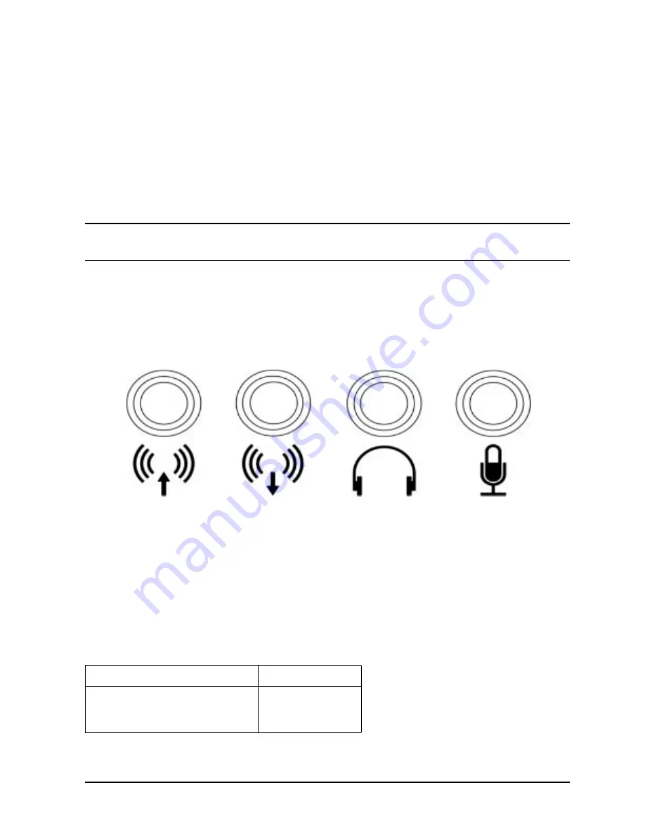
Audio Connectors
Your workstation has audio input and output capability through external input and output
connectors on the rear panel and through an internal speaker. The rear panel contains the
line input jack, line output jack, headphone jack, and microphone jack connectors.
Figure 1-6. Audio Connectors
The audio connectors are standard stereo audio mini-jacks. Hewlett-Packard recommends
using gold-plated plugs available through audio retailers for best quality recording and
playback through the external connectors. Table 1-4 on the next page provides a summary
of the audio electrical specifications.
Table 1-4. Audio Electrical Specifications
Frequency Response
25 Hz to 20 kHz
Input Sensitivity/Impedance:
– Line in
– Microphone
2.0 Vpk/47 Kohm
22 mVpk/1 Kohm
Line Input
Line Output
Headphone
Microphone
Содержание Visualize j6000
Страница 8: ...8 Contents ...
Страница 30: ...30 Chapter1 Product Information Monitors ...
Страница 37: ...Chapter 3 37 Troubleshooting Flowcharts for Troubleshooting Figure 3 1 Main Flowchart for Troubleshooting ...
Страница 38: ...38 Chapter3 Troubleshooting Flowcharts for Troubleshooting Figure 3 2 Console Troubleshooting Flowchart ...
Страница 40: ...40 Chapter3 Troubleshooting Flowcharts for Troubleshooting Figure 3 4 HP UX Troubleshooting Flowchart ...
Страница 76: ...76 Chapter3 Troubleshooting Using the System Board LEDs for Troubleshooting ...
Страница 100: ...100 Chapter4 Field Replaceable Units FRUs FRU Removal and Replacement ...
Страница 134: ...134 Chapter5 Boot Console Handler Initial System Loader ISL Environment ...
Страница 135: ...135 6 Block Diagram This chapter contains the block diagram for the J6000 workstation s system board and PCI board ...


