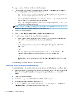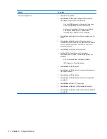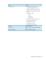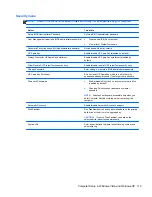
Before removing the system board, follow these steps:
1.
Shut down the computer. If you are unsure whether the computer is off or in Hibernation, turn
the computer on, and then shut it down through the operating system.
2.
Disconnect all external devices connected to the computer.
3.
Disconnect the power from the computer by first unplugging the power cord from the AC outlet
and then unplugging the AC adapter from the computer.
4.
Remove the battery (see
Battery on page 57
).
5.
Remove the following components:
a.
SIM (see
SIM on page 58
)
b.
Switch cover (see
Switch cover on page 59
)
c.
Keyboard (see
Keyboard on page 61
)
d.
Speakers (see
Speakers on page 68
)
e.
WWAN module (see
WWAN module on page 70
)
f.
Palm rest (see
Palm rest on page 72
)
g.
Bluetooth module and cable (see
Bluetooth module on page 81
)
h.
WLAN module (see
WLAN module on page 77
)
i.
Hard drive (see
Hard drive on page 74
)
j.
Optical drive (see
Optical drive on page 65
)
k.
Display assembly (see
Display assembly on page 91
)
l.
Top cover (see
Top cover on page 99
)
m.
Power connector and cable
When replacing the system board, be sure that the following components are removed from the
defective system board and installed on the replacement system board:
●
Memory module (see
Memory module on page 63
)
●
WLAN module (see
WLAN module on page 77
)
●
WWAN module (see
WWAN module on page 70
)
●
Modem module (see
Modem module on page 101
)
●
Processor (see
Processor on page 87
)
Remove the system board:
1.
Position the computer right-side up with the front toward you.
2.
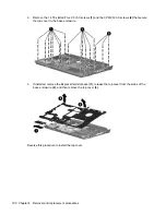
Remove the T8 slotted-Torx 2.5×5.0 screw
(1)
that secures the system board to the base
enclosure.
3.
Disconnect the USB board cable from the system board
(2)
.
104 Chapter 4 Removal and replacement procedures
Содержание ProBook 4320s
Страница 4: ...iv Safety warning notice ...
Страница 31: ...Computer major components Computer major components 23 ...
Страница 157: ...Audio out headphone Pin Signal 1 Audio out left channel 2 Audio out right channel 3 Ground Audio out headphone 149 ...
Страница 160: ...RJ 11 modem Pin Signal 1 Unused 2 Tip 3 Ring 4 Unused 5 Unused 6 Unused 152 Chapter 8 Connector pin assignments ...
Страница 176: ......


