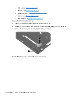
c.
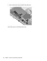
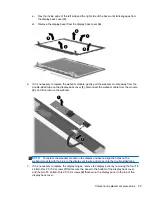
Flex the inside edge of the left side and the right side of the bezel until it disengages from
the display back cover
(3)
.
d.
Remove the display bezel from the display back cover
(4)
.
6.
If it is necessary to replace the webcam module, gently pull the webcam module away from the
double-sided tape on the display back cover
(1)
, disconnect the webcam cable from the module
(2)
, and then remove the webcam.
NOTE:
To replace the webcam module in the display enclosure, align the holes on the
webcam module with the pins on the display enclosure and press onto the double-sided tape.
7.
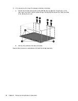
If it is necessary to replace the display hinges, remove the display panel by removing the four T8
slotted-Torx 2.5×5.0 screws
(1)
that secure the panel to the bottom of the display back cover
and the two T8 slotted-Torx 2.5×3.0 screws
(2)
that secure the display panel to the top of the
display back cover.
Component replacement procedures
95
Содержание ProBook 4320s
Страница 4: ...iv Safety warning notice ...
Страница 31: ...Computer major components Computer major components 23 ...
Страница 157: ...Audio out headphone Pin Signal 1 Audio out left channel 2 Audio out right channel 3 Ground Audio out headphone 149 ...
Страница 160: ...RJ 11 modem Pin Signal 1 Unused 2 Tip 3 Ring 4 Unused 5 Unused 6 Unused 152 Chapter 8 Connector pin assignments ...
Страница 176: ......


